EXPLANATORY NOTES ON THE MAINTENANCE ACTIVITIES
Inspection and adjustment 95XF series
3-10
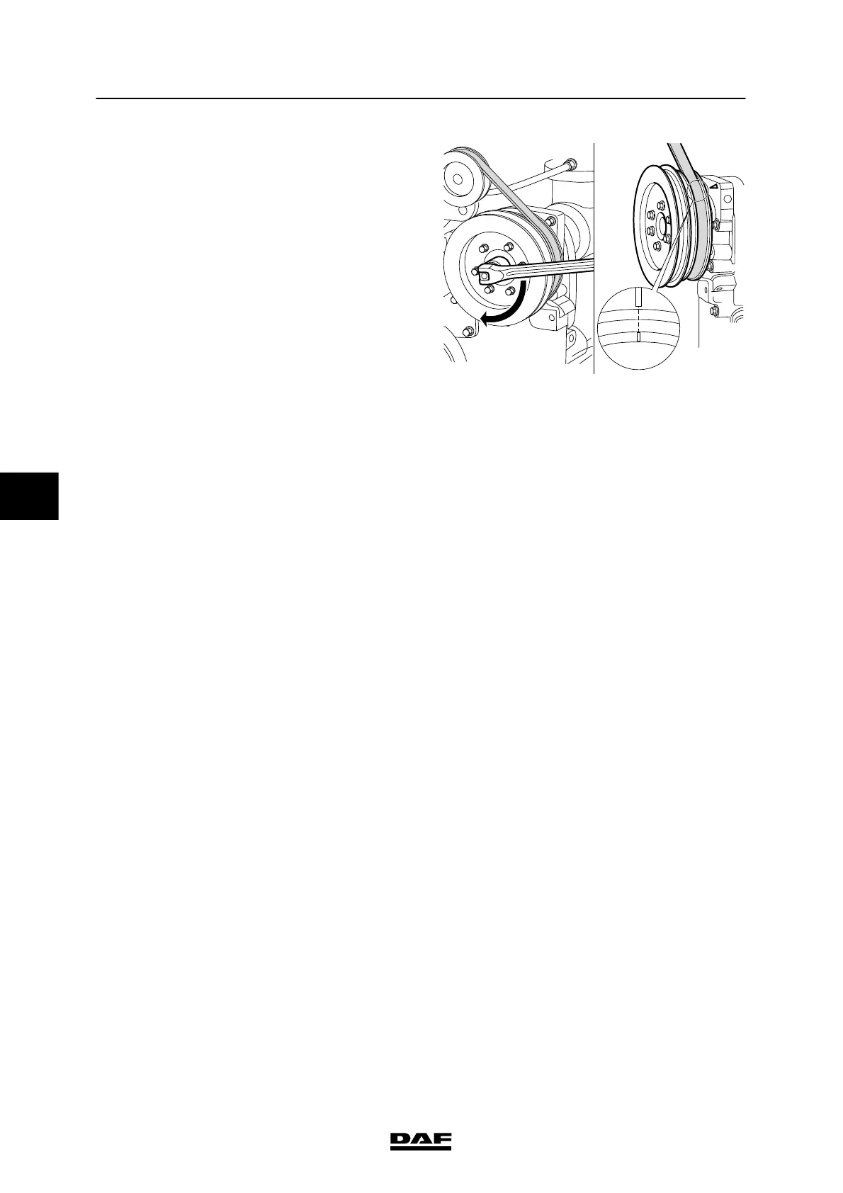
7. Rotate the drive pulley (in the direction of
rotation of the crankshaft) using the
attachment nut on the pulley, until the “A”
marking is in line with the marking on the
timing cover.
8. Check that the inlet and exhaust valves of
cylinder 1 are closed.
Note:
The valves are closed if both rockers can be
moved from side to side.
If necessary, rotate the drive pulley through
360_ until the “A” marking is once again in
line with the marking on the cylinder block.
9. Now adjust the valve clearance and the unit
injector of cylinder 1.
10. Repeat this adjustment procedure for the
remaining cylinders. Consult the following
table to this end.
Marks on drive pulley:
Adjustment of inlet and exhaust valves and
unit injectors of cylinder:
A1or6
B5or2
C3or4
11. If required, fit the C-brake, s ee chapter
“Removal and Installation”.
12. Fit the v alve covers. See “Removal and
installation”.
A
M2142
5
200424