16 Spyder3 S3-14 and S3-24 Monochrome Camera User's Manual
03-032-20117-01 Teledyne DALSA
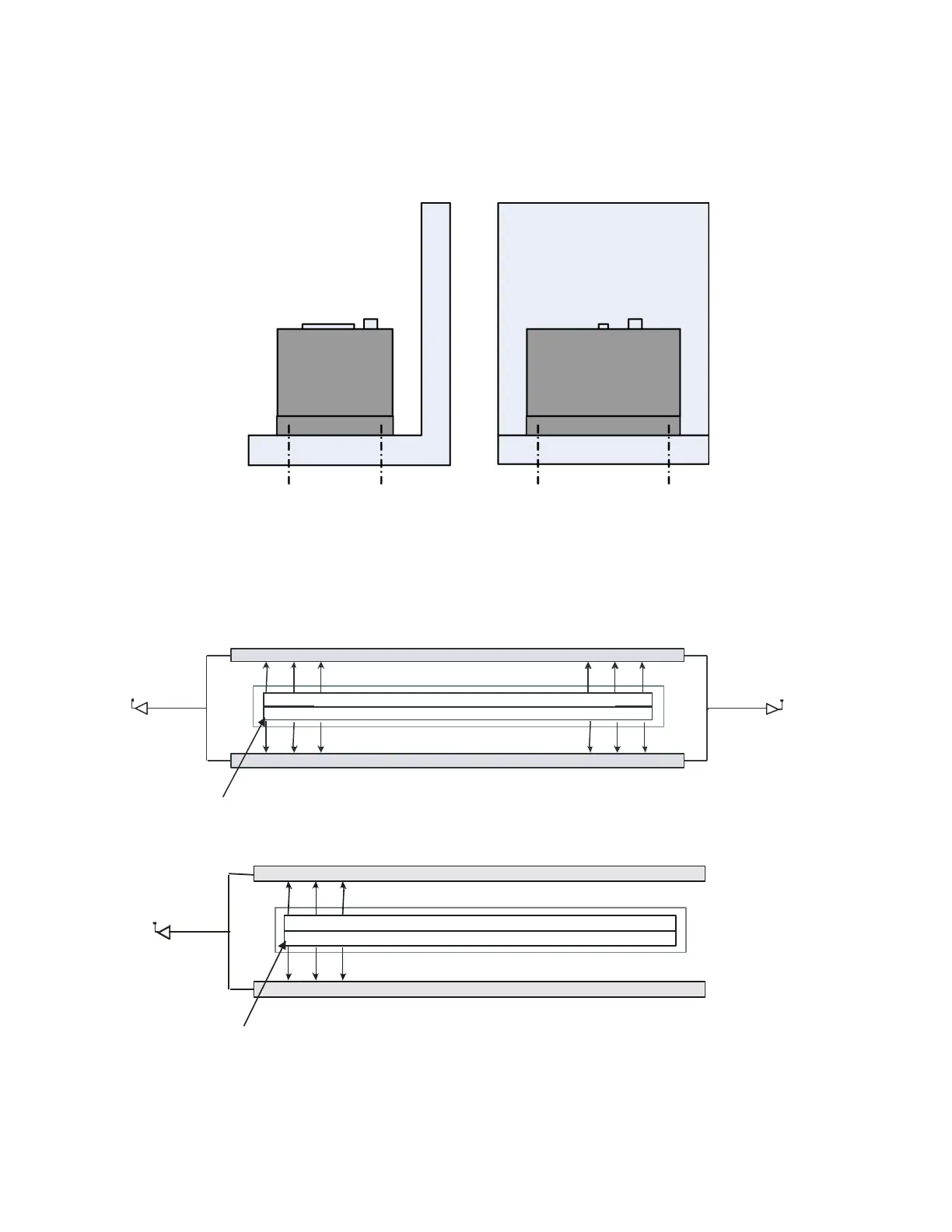
Mounting
Heat generated by the camera must be allowed to move away from the camera. Mount the camera on the
front plate (using the provided mounting holes) with maximum contact to the area for best heat
dissipation.
Figure 7: Spyder3 Mounting Example
Image Sensor
The camera uses Teledyne DALSA’s d ual line scan sensor. The camera can be configured to read out in
either high or low sensitivity mode, tall pixel mode, and either forward or reverse shift direction.
Figure 8: 2 Tap Sensor Block Diagram
Tap 2Tap 1
CCD Readout Shift Register
CCD Readout Shift Register
N
Pixels
N
Pixels
N
=1024, 2048, 4096
Pixel 1, 1
Figure 9: 1 Tap Sensor Block Diagram (1k and 2k only)
Tap 1
CCD Readout Shift Register
CCD Readout Shift Register
N
Pixels (14µm x 14µm)
N
Pixels (14µm x 14µm)
N
=1024, 2048
Pixel 1, 1

 Loading...


