Spyder3 S3-14 and S3-24 Monochrome Camera User's Manual 19
Teledyne DALSA 03-032-20117-01
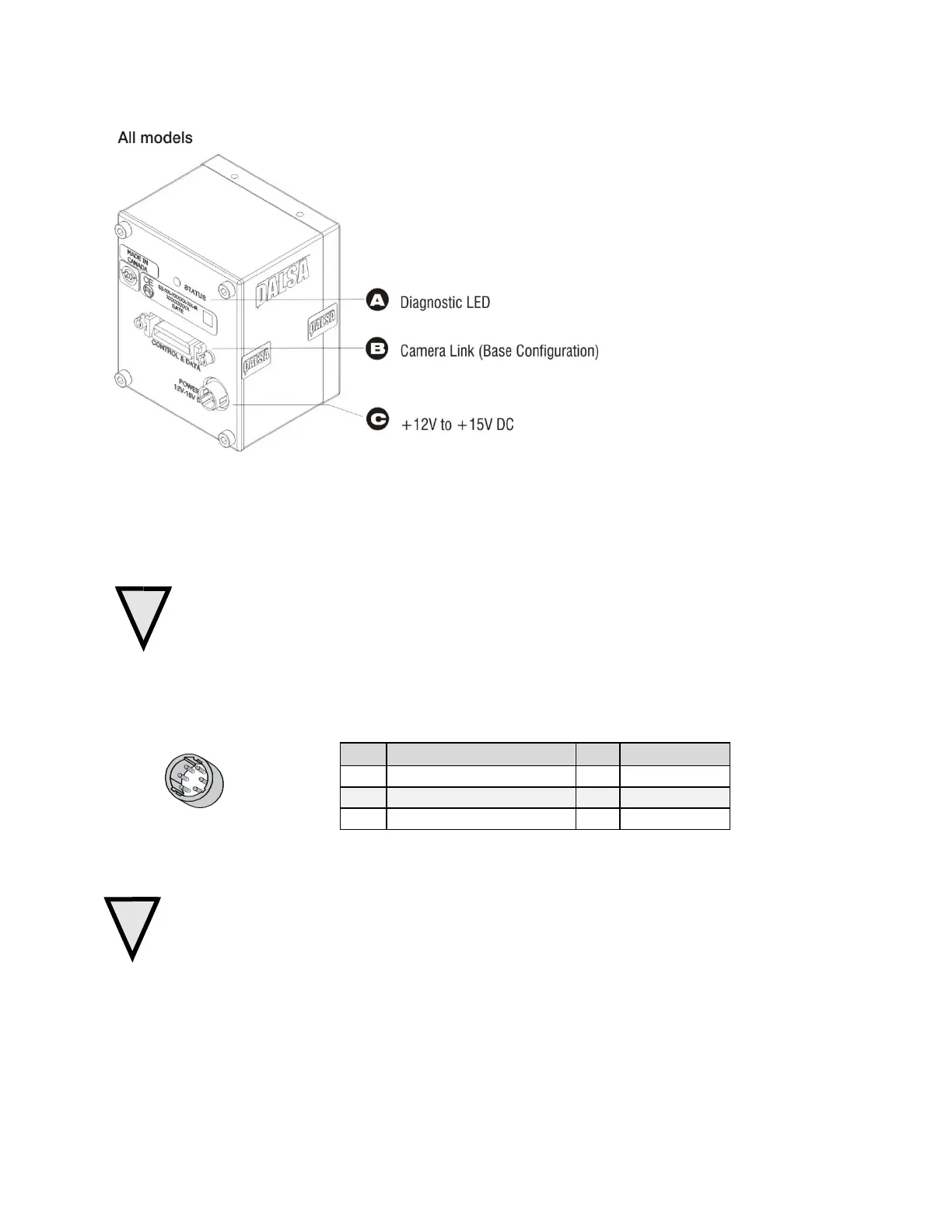
Figure 10: Hirose 6-pin Circular Male—Power Connector
Power Connector
WARNING: It is extremely important that you apply the appropriate voltages to your camera.
Incorrect voltages may damage the camera. Input voltage requirement: +12 V to +15 V DC.
The camera requires a single 6-pin Hirose connector with a single voltage input +12 VDC to
+15 VDC for power. The camera meets all performance specifications using standard switching power
supplies, although well-regulated linear supplies provide optimum performance.
Hirose 6-pin Circular Male
5
4
6
2
3
1
Mating Part: HIROSE
HR10A-7P-6S
WARNING: When setting up the camera’s power supplies follow these guidelines:
Apply the appropriate voltages.
Protect the camera with a 2 amp slow-blow fuse between the power supply and the camera.
Do not use the shield on a multi-conductor cable for ground.
Keep leads as short as possible in order to reduce voltage drop.
Use high-quality linear supplies in order to minimize noise.
Note: If your power supply does not meet these requirements, then the camera performance specifications are not
guaranteed.
Table 5: Hirose Pin Description

 Loading...


