Spyder3 S3-14 and S3-24 Monochrome Camera User's Manual 69
Teledyne DALSA 03-032-20117-01
Voltage Measurement
The command vv disp lays the camera’s inp ut voltage. N ote that the voltage measurem ent featu re of the
camera provides only approximate results (typically within 10%). The measurement should not be used
to set the applied voltage to the camera but only used as a test to isolate gross problems with the supply
voltage.
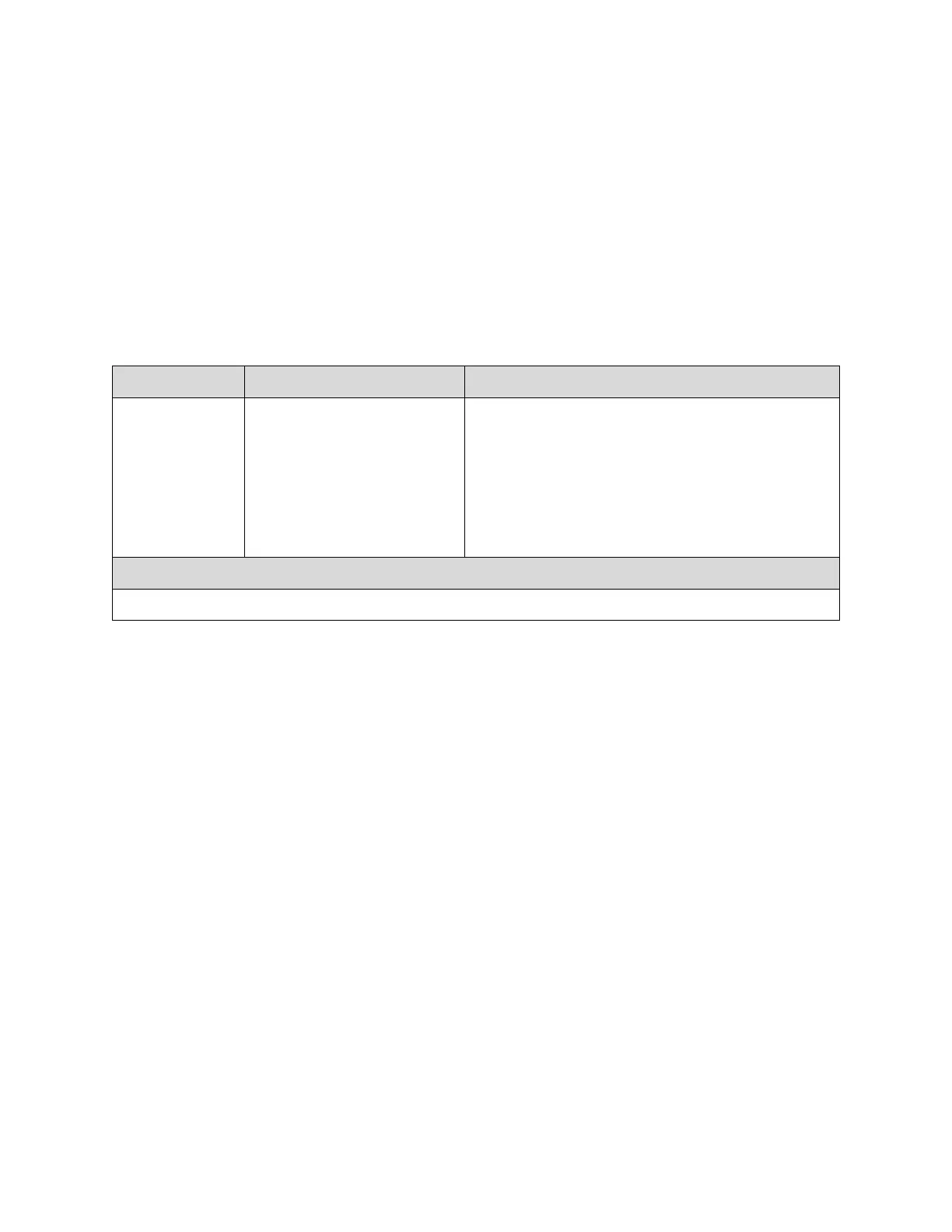
Camera Frequency Measurement
Returns the frequency for the requested Camera Link control signal
Camera Link Command
Camera Link control signal to
measure:
1: CC1 (EXSYNC)
2: CC2 (PRIN)
3: CC3 (CCD Direction)
Camera operation may be impacted when
entering the gsf command (i.e., poor time
response to direction change or video may have
artifacts (gain changes) for several lines while
the camera returns signal information)
This command is not available when operating the
camera with external CCD direction control (scd
2)

 Loading...


