86 Spyder3 S3-14 and S3-24 Monochrome Camera User's Manual
03-032-20117-01 Teledyne DALSA
Camera Control Signals
Four LVDS pairs are reserved for general purpose camera control. They are defined as camera inputs and
frame grabber outputs. Camera manufacturers can define these signals to meet their needs for a
particular product. The signals are:
• Camera Control 1 (CC1)
• Camera Control 2 (CC2)
• Camera Control 3 (CC3)
• Camera Control 4 (CC4)
The S3-xx uses the following camera control signals:
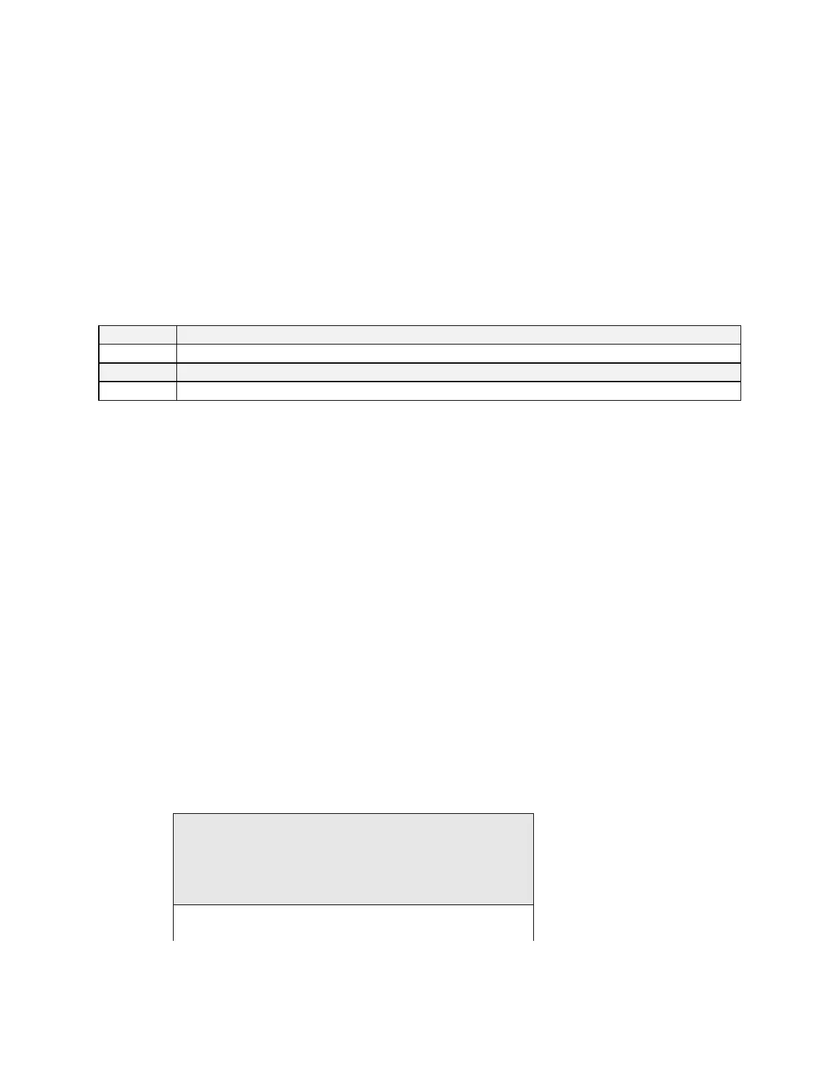
Table 20: Teledyne DALSA Camera Control Configuration
EXSYNC, negative edge active
Direct in High Sensitivity mode
Communication
Two LVDS pairs have been allocated for asynchronous serial communication to and from the camera and
frame grabber. Cameras and frame grabbers should support at least 9600 baud. These signals are
• SerTFG—Differential pair with serial communications to the frame grabber.
• SerTC—Differential pair with serial communications to the camera.
The serial interface will have the following characteristics: one start bit, one stop bit, no parity, and no
handshaking. It is recommended that frame grabber manufacturers supply both a user interface and a
software application programming interface (API) for using the asynchronous serial communication port.
The user interface will consist of a terminal program with minimal capabilities of sending and receiving a
character string and sending a file of bytes. The software API will provide functions to enumerate boards
and send or receive a character string.
Power
Power will not be provided on the Camera Link connector. The camera will receive power through a
separate cable. Camera manufacturers will define their own power connector, current, and voltage
requirements.
Camera Link Bit Definitions

 Loading...


