104 • Appendix: X-I/O Module Option X64 Xcelera-CL PX4 User's Manual
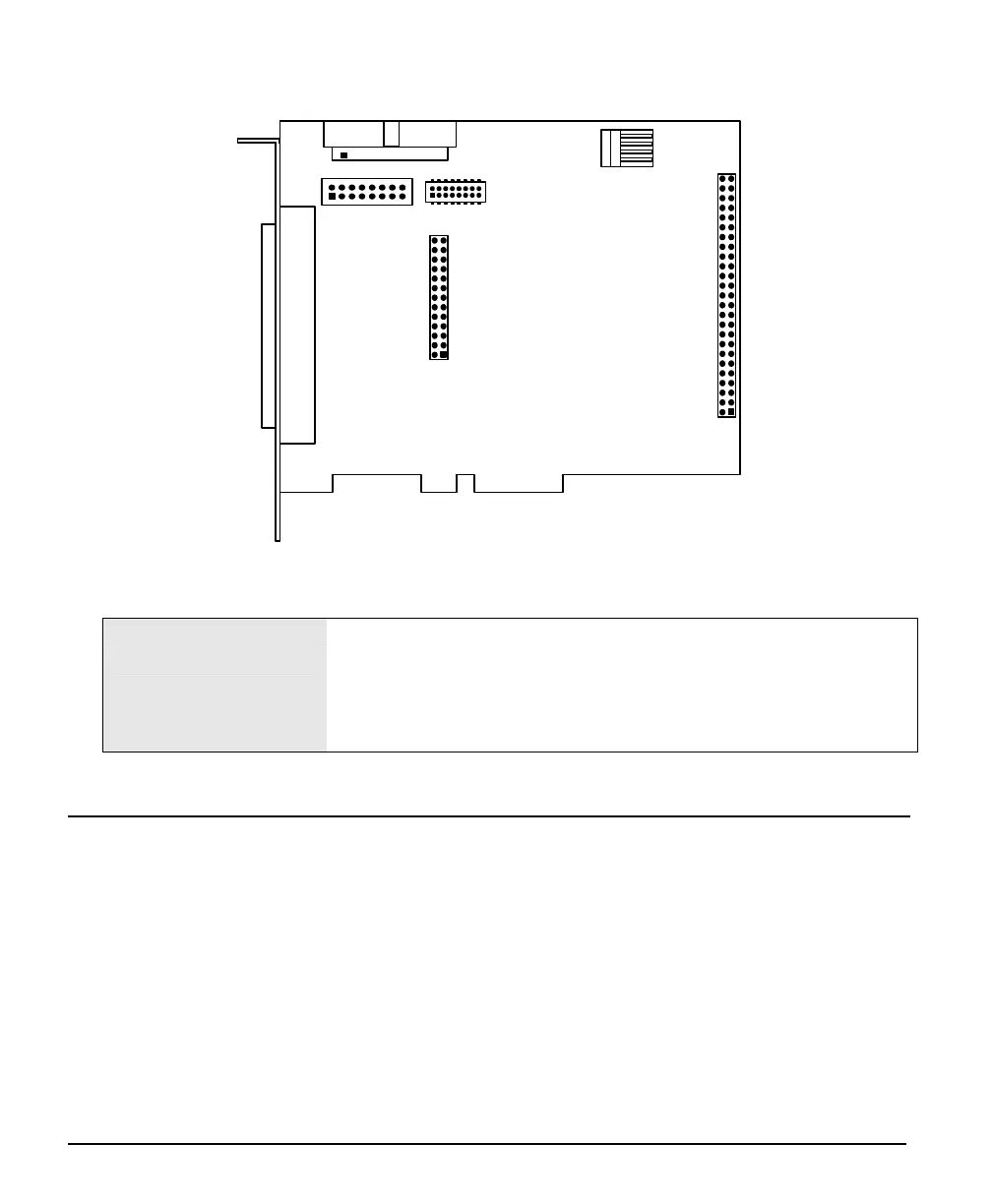
X-I/O Module Connector List & Locations
DB37 female
J21
J22
J23
J24
J20
J26
J28
X-I/O revision A2
J20 DB37 female external signals connector.
J23
16 pin header connector
(interconnect to the X64 Xcelera-CL PX4 via supplied ribbon cable).
J21, J22, J24, J28 Reserved.
J26 Connect PC power via floppy drive power cable.
X-I/O Module Installation
Grounding Instructions: Static electricity can damage electronic components. Please discharge any
static electrical charge by touching a grounded surface, such as the metal computer chassis, before
performing any hardware installation. If you do not feel comfortable performing the installation, please
consult a qualified computer technician. Never remove or install any hardware component with the
computer power on.