108 • Appendix: X-I/O Module Option X64 Xcelera-CL PX4 User's Manual
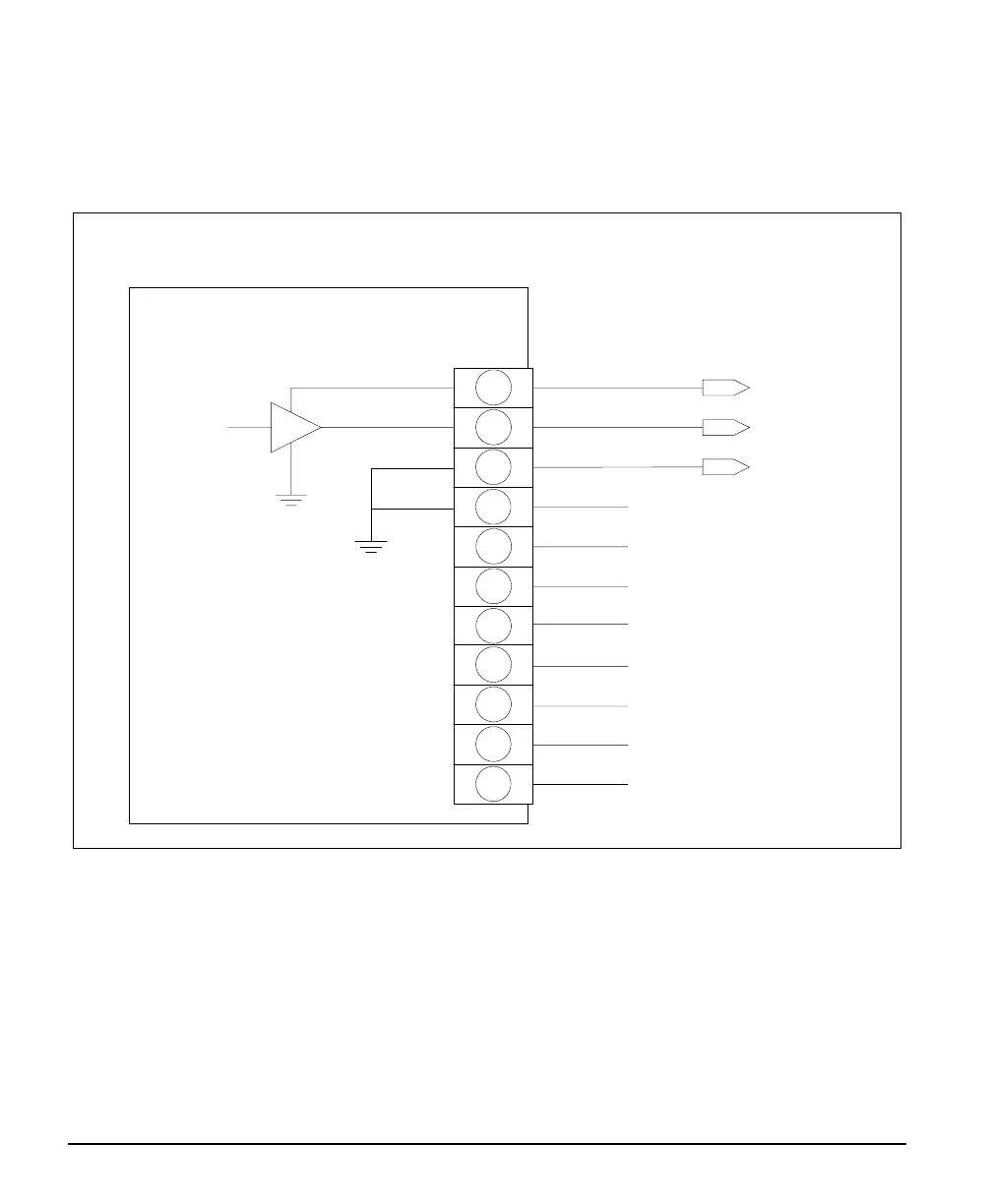
TTL Output in PNP Mode: Electrical Details
When the TTL outputs are configured for PNP mode (source driver) an external power supply is required
to provide the buffer output supply voltage (USER_PWR). A simplified schematic and important output
specifications follow:
Output 1
Output 2
Output 3
Output 4
Output 5
Output 6
Output 7
Output 8
GND
GND
Device Input
Device Input GND
DB37
Connector
Simplified
Output Buffer
Driver
typical 8 places
X-I/O Module
22
3, 23, 24
4
35
17
36
18
37
19
16, 29, 30
PNP Source Driver Output Mode
Device Power Supply
USER_PWR
5
Buffer Vcc
• User provides the output power supply voltage ( 7 volts to 35 volts ).
• Maximum source driver output current is 350 mA.
• Source driver with over-current protection (all outputs will shut down simultaneously). The
over-current fault circuit will protect the device from short-circuits to ground with supply
voltages of up to 35V.