82 • Technical Specifications X64 Xcelera-CL PX4 User's Manual
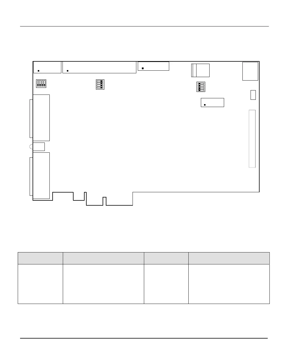
Connector and Switch Locations
X64 Xcelera-CL PX4 Board Layout Drawing
J3
J10
LED 1
J7
J2000
J2
J4
X64 Xcelera-CL PX4 Full
SW1
J9
PCIe 4X
J1
J6
J8
SW2
SW3
Connector Description List
The following table lists components on the X64 Xcelera-CL PX4 board. Detailed information follows
for connectors or switches the end user may have need of.
Connector Description Connector Description
J2 Camera Link Connector J6 X-I/O Module Interface
J3 Camera Link Connector J7 PC power to camera interface.
J4 External Signals connector
J1, J8, J9
J10, J2000
Reserved
SW1, SW2, SW3 Configuration micro-switches