X64 Xcelera-CL PX4 User's Manual X64 Xcelera-CL PX4 Reference • 47
Shaft Encoder Interface Timing
Connector J4, Dual Balanced Shaft Encoder Inputs:
• Input 1: Pin 23 (Phase A +) & Pin 24 (Phase A -)
(see "J4: External Signals Connector " on
page 89 for complete connector signal details)
• Input 2: Pin 25 (Phase B +) & Pin 26 (Phase B -)
• See “External Signals Connector Bracket Assembly” on p
age 94 for pinout information about
the DB37 used for external connections.
Web inspection systems with variable web speeds typically provide one or two synchronization signals
from a web mounted encoder to coordinate trigger signals. These trigger signals are used by the
acquisition linescan camera. The X64 Xcelera-CL PX4 supports single or dual shaft encoder signals.
Dual encoder signals are typically 90 degrees out of phase relative to each other and provide greater web
motion resolution.
When enabled, the camera is triggered and acquires one scan line for each shaft encoder pulse edge. To
optimize the web application, a second Sapera parameter defines the number of triggers to skip between
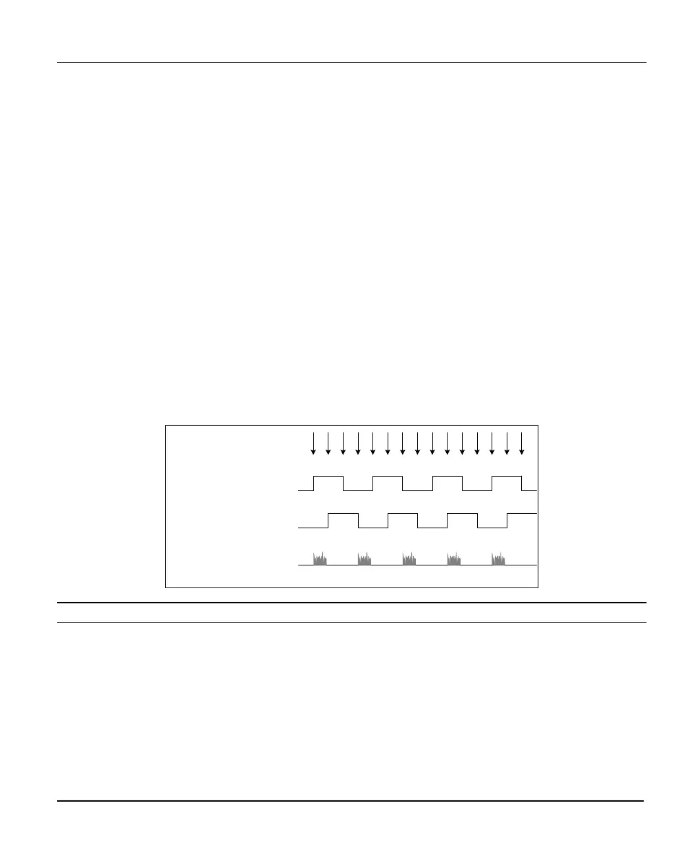
valid acquisition triggers. The figure below depicts a system where a valid camera trigger is any pulse
edge from either shaft encoder signal. After a trigger the two following triggers are ignored (as defined by
the Sapera pulse drop parameter).
K D D K D D K D D K D D K D D
Shaft Encoder phase A
Shaft Encoder phase B
K = Keep
D = Drop or Skip
Note: in this example, Number of trigger to drop = 2
Line acquired
Note that camera file parameters are best modified by using the Sapera CamExpert program.