X64 Xcelera-CL PX4 User's Manual Technical Specifications • 83
Connector and Switch Specifications
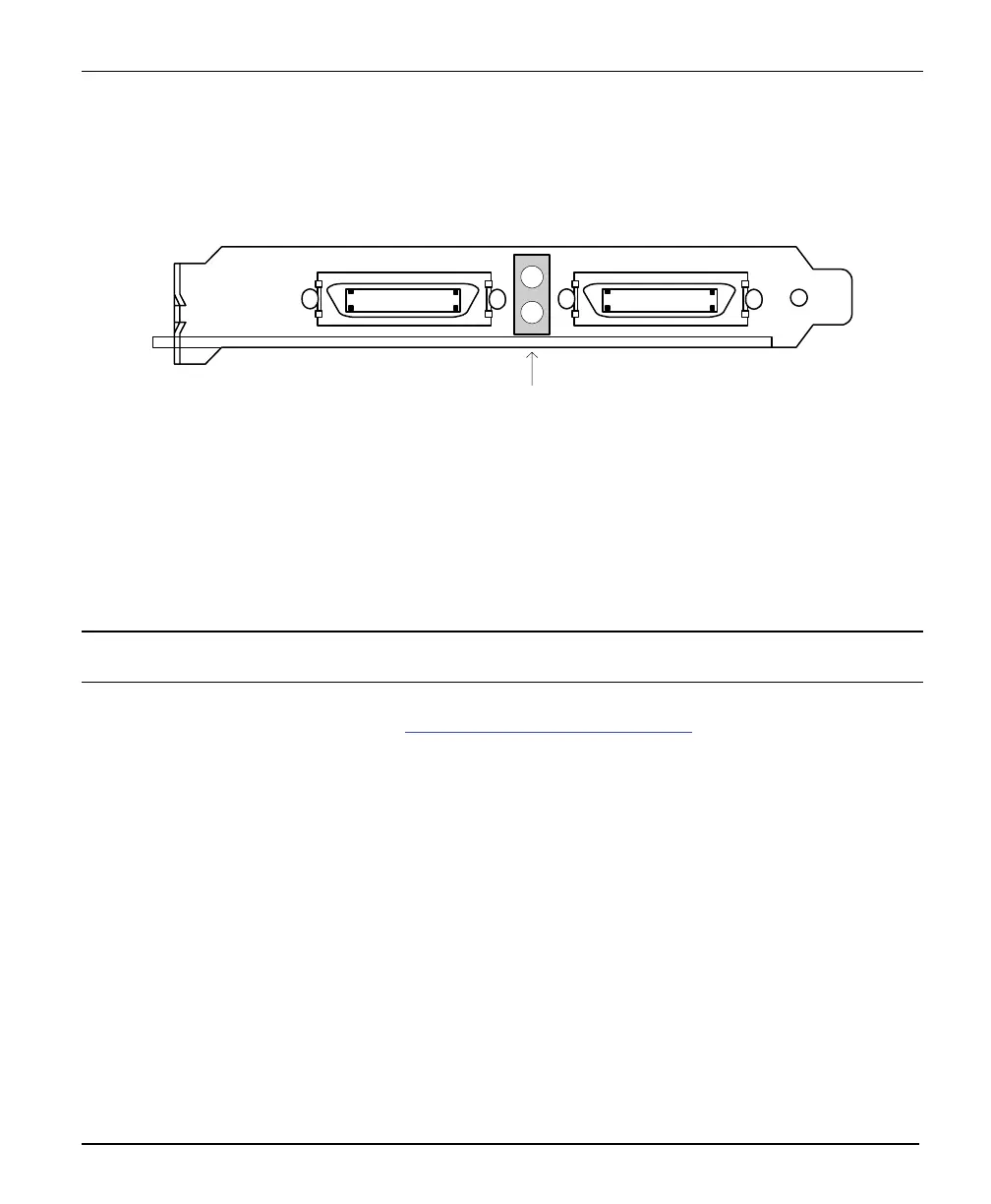
X64 Xcelera-CL PX4 End Bracket Detail
Camera Link 1
3M MDR 26 pin female
connector
X64 Xcelera-CL PX4
Camera Link 2
3M MDR 26 pin female
connector
LEDs
1
14
13
26
1
14
13
26
1
2
The hardware installation process is completed with the connection of a supported camera to the X64
Xcelera-CL PX4 board using Camera Link cables (see “Camera Link Cables” on
page 101).
• The X64 Xcelera-CL PX4 board supports a camera with one or two Camera Link MDR-26
connectors (two Base or one Medium – see “Data Port Summary”
on page 100 for information
on Camera Link configurations).
• Connect the camera to the J1 connector with a Camera Link cable. When using a Medium
camera, connect the second camera connector to J2.
Note: If the camera is powered by the X64 Xcelera-CL PX4, refer to "External Signals Connector Bracket
Assembly" on page 94 for power connections.
Contact DALSA or browse our web site http://www.imaging.com/camsearch for the latest information on
X64 Xcelera-CL PX4 supported cameras.