X64 Xcelera-CL PX4 User's Manual Technical Specifications • 89
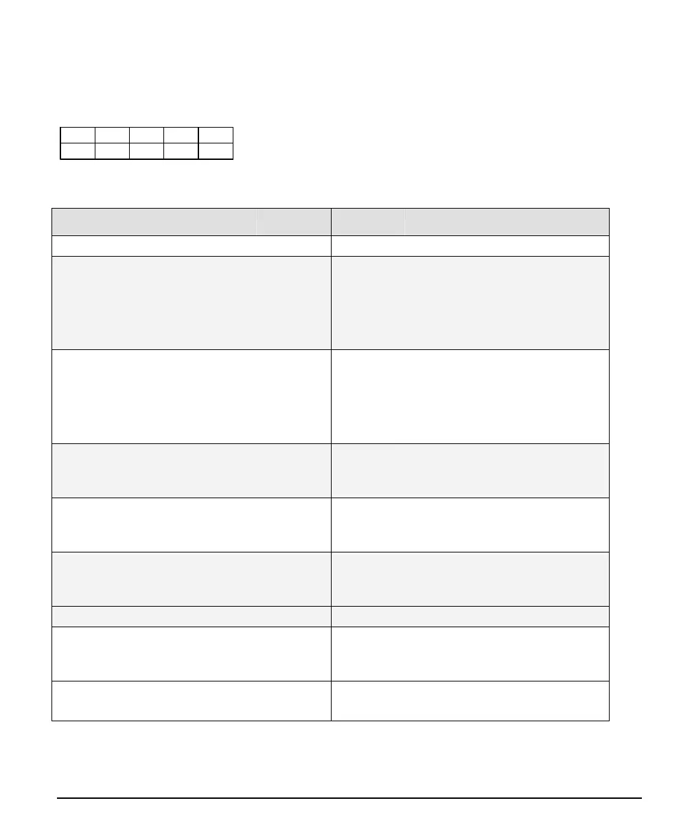
J4: External Signals Connector
J4 Pin Header Numbering Detail
2
4
...
38 40
1
3
...
37 39
J4 Signal Descriptions
Description Pin # Pin # Description
Ground 1 2 Ground
General Input 0 +
(see note 1)
3 4 General Input 0 -
General Input 1 + 5 6 General Input 1 -
General Input 2 + 7 8 General Input 2 -
General Input 3 + 9 10 General Input 3 -
General Output 0 +
(see note 2)
11 12 General Output 0 -
General Output 1 + 13 14 General Output 1 -
General Output 2 + 15 16 General Output 2 -
General Output 3 + 17 18 General Output 3 -
External Trigger Input 0 +
(see note 3)
19 20 External Trigger Input 0 -
External Trigger Input 1 + 21 22 External Trigger Input 1 -
Shaft Encoder Phase A +
(see note 4)
23 24 Shaft Encoder Phase A -
Shaft Encoder Phase B + 25 26 Shaft Encoder Phase B -
Ground 27 28
Strobe Output 0
(see note 5)
Ground 29 30 Strobe Output 1
Ground 31 32 Ground
Power Output 5 Volts, 1.5A max
(see note 6)
33 34 Power Output 5 Volts, 1.5A max
Power Output 12 Volts, 1.5A max 35 36 Power Output 12 Volts, 1.5A max
Ground 37 38 Ground
Ground 39 40 Ground