90 • Technical Specifications X64 Xcelera-CL PX4 User's Manual
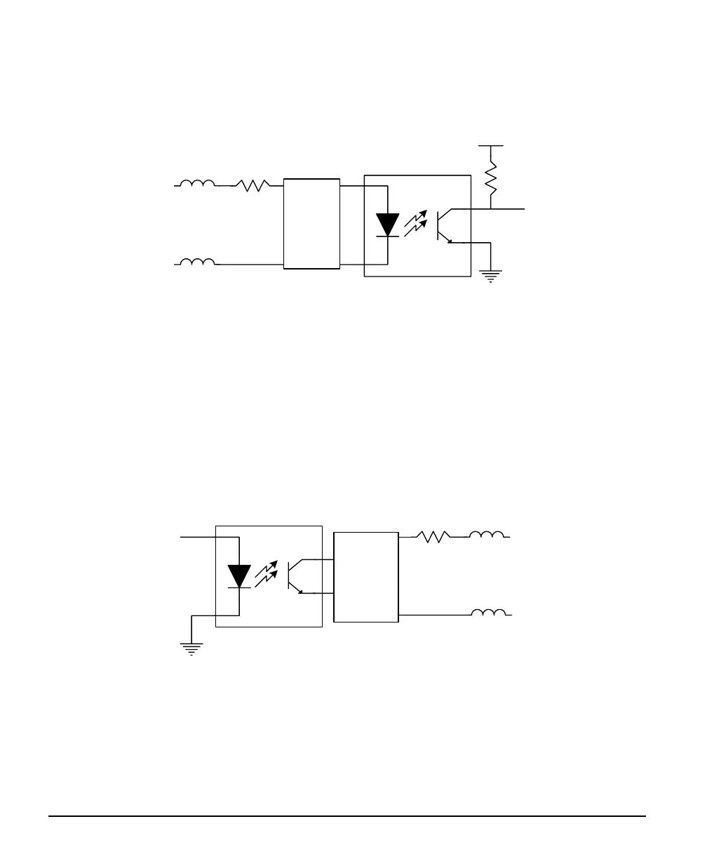
Note 1: General Inputs Specifications
Each of the four General Inputs are opto-coupled and able to connect to differential signals (LVDS or
RS422) or single ended TTL source signals. These inputs generate individual interrupts and are read by
the Sapera application. The following figure is typical for each Genera Input.
V+
FB
FB
Gin +
650
nGin
Gin -
noise filter
&
level
select
(SW1)
Input Details:
• For single ended TTL signals, the Gin- pin is connected to ground. The switch point is ~10V by
default and can be change to ~2V with SW1.
• Each input has a ferrite bead plus a 650 ohm series resistor on the opto-coupler anode.
• Each input provides some high frequency noise filtering.
• Maximum input signal frequency is 25 KHz.
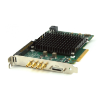
Note 2: General Outputs Specifications
Each of the four General Outputs are opto-coupled. Each output is an isolated open-collector NPN
transistor switch. The following figure is typical for each General Output.
FB
680
Gout
Gout -
FB
Gout +
reverse
voltage
protection
& filter
Output Details:
• Each output has ferrite beads plus a 680 ohm series resistor on the cathode (+) connection.
• Maximum output device differential voltage is 25V.
• Maximum output device sink current is 35mA with 25V output differential.
• Maximum reverse voltage is 25V.
• Maximum output switching frequency is limited by driver and register access on the PCIe bus.