84 • Technical Specifications X64 Xcelera-CL PX4 User's Manual
Configuration Micro-switches
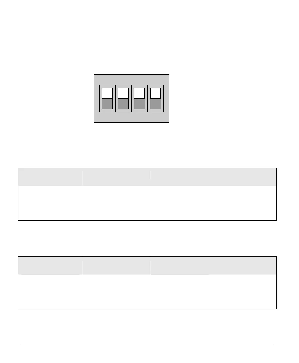
Three sets of 4 switches are used for user configurations not controlled by software. The following figure
is a typical view of each switch set, shown with the individual switch set in the OFF position. Following
the figure, each of the three switch sets is described. Refer to the board component layout for their
positions.
OFF
ON
1234
SW1, SW2, SW3 Component View
SW1: General Inputs Signal Switch Point
For each general input, select the threshold voltage detected as a logic high signal. See "Note 1: General
Inputs Specifications" on page 90.
SW1
Switch Number
Assigned to OFF Position ON Position
(default)
1
2
3
4
general input 1
general input 2
general input 3
general input 4
Logic Transition at
~2 volts
(preferred for differential
signals)
Logic Transition at
~10 volts
SW2: Trigger Inputs Signal Switch Point
For each trigger input, select the threshold voltage detected as a logic high signal. See "Note 3: External
Trigger Input Specifications" on page 91.
SW2
Switch Number
Assigned to OFF Position
(default)
ON Position
1
2
3
4
trigger input 1
trigger input 2
NA
NA
Logic Transition at
~2 volts
(preferred for differential
signals)
Logic Transition at
~10 volts