X64 Xcelera-CL PX4 User's Manual Technical Specifications • 91
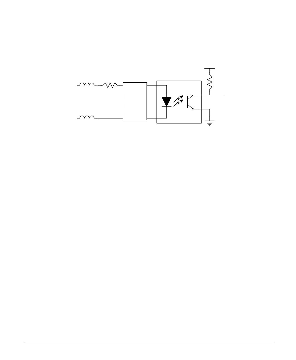
Note 3: External Trigger Input Specifications
The two Trigger Inputs are opto-coupled and compatible to differential signals (LVDS or RS422) or
single ended TTL source signals. The following figure is typical for each External Trigger Input.
V+
FB
FB
Trig In +
650
nTrig
Trig In -
noise filter
&
level
select
(SW2)
• For single ended TTL signals, the TrigIn- pin is connected to ground. The switch point is ~10V by
default and can be change to ~2V with SW2.
• The incoming trigger pulse is software “debounced” to ensure that no voltage glitch is detected as a
valid trigger pulse. This debounce circuit time constant can be programmed from 0ms to 255ms. Any
pulse smaller than the programmed value is blocked and therefore not seen by the acquisition
circuitry.
• Each input has a ferrite bead plus a 650 ohm series resistor on the opto-coupler anode.
• Maximum input signal frequency is 200 KHz.
• Refer to Sapera parameters:
CORACQ_PRM_EXT_TRIGGER_SOURCE
CORACQ_PRM_EXT_TRIGGER_ENABLE
CORACQ_PRM_EXT_TRIGGER_LEVEL
CORACQ_PRM_EXT_FRAME_TRIGGER_LEVEL
CORACQ_PRM_EXT_TRIGGER_DETECTION
CORACQ_PRM_EXT_TRIGGER_DURATION
• See also *.cvi file entries:
External Trigger Level, External Frame Trigger Level, External Trigger Enable, External Trigger
Detection.
• External Trigger Input 2 used for two pulse external trigger with variable frame length linescan
acquisition.