92 • Technical Specifications X64 Xcelera-CL PX4 User's Manual
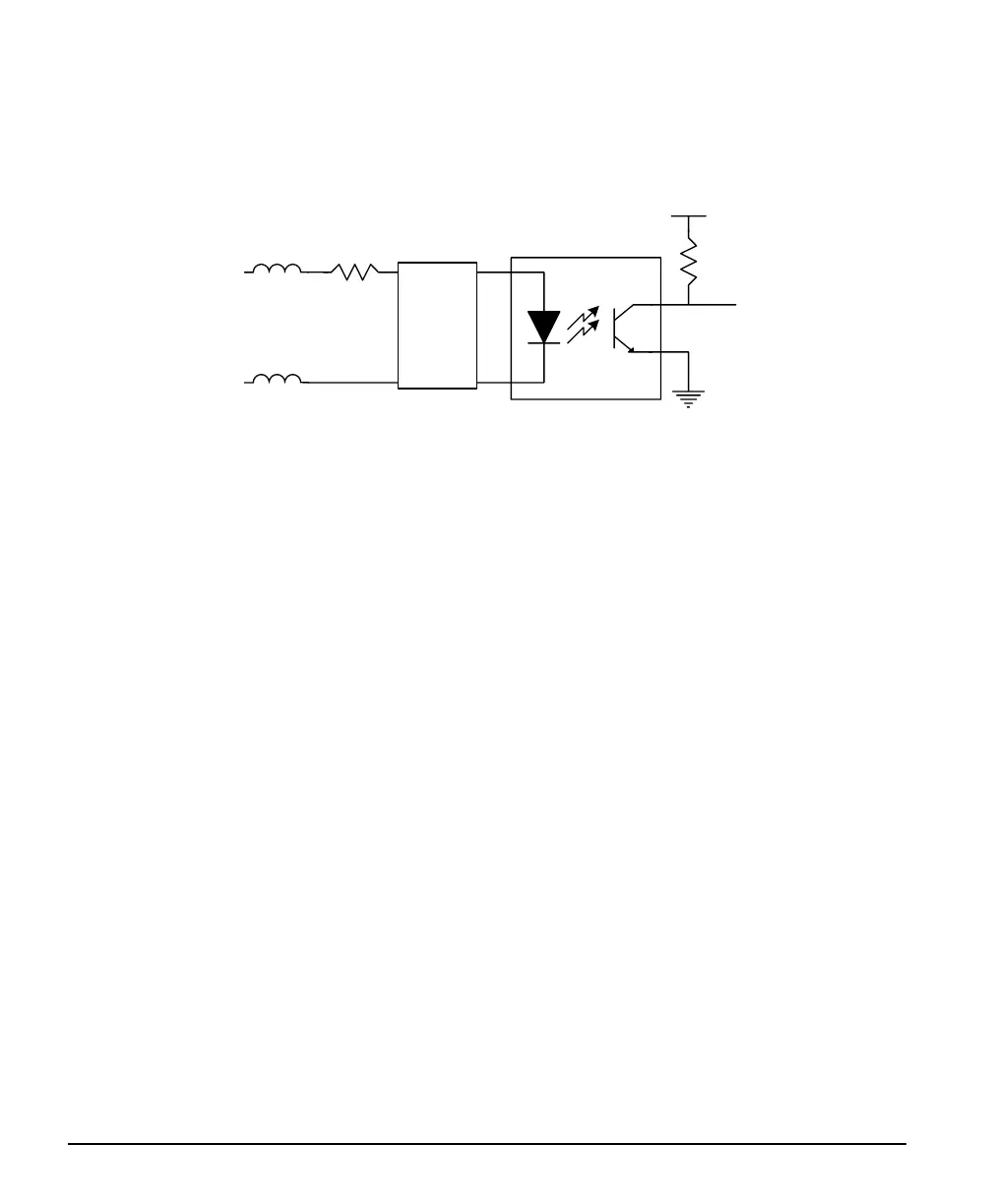
Note 4: Shaft Encoder Input Specifications
Dual Quadrature Shaft Encoder Inputs (phase A and phase B) are opto-coupled and able to connect to
differential signals (LVDS or RS422) or single ended TTL source signals. The following figure is typical
for each input.
V+
FB
FB
SE +
220
nSE
SE -
noise filter
• For single ended TTL signals, the SE- pin is connected to ground. The switch point is ~2V.
• Each input has a ferrite bead plus a 220 ohm series resistor on the opto-coupler anode.
• Maximum input signal frequency is 200 KHz.
• See "Line Trigger Source Selection for Linescan Applications" on page 45 for more information.
• Refer to Sapera parameters:
CORACQ_PRM_SHAFT_ENCODER_ENABLE CORACQ_PRM_SHAFT_ENCODER_DROP
or refer to CORACQ_PRM_EXT_LINE_TRIGGER_ENABLE
CORACQ_PRM_EXT_LINE_TRIGGER_DETECTION
CORACQ_PRM_EXT_LINE_TRIGGER_LEVEL (fixed at LVDS)
CORACQ_PRM_EXT_LINE_TRIGGER_SOURCE
• See also *.cvi file entries:
Shaft Encoder Enable, Shaft Encoder Pulse Drop
or see External Line Trigger Enable, External Line Trigger Detection, External Line Trigger Level,
External Line Trigger Source.