X64 Xcelera-CL PX4 User's Manual Technical Specifications • 93
Note 5: Strobe Output Specifications
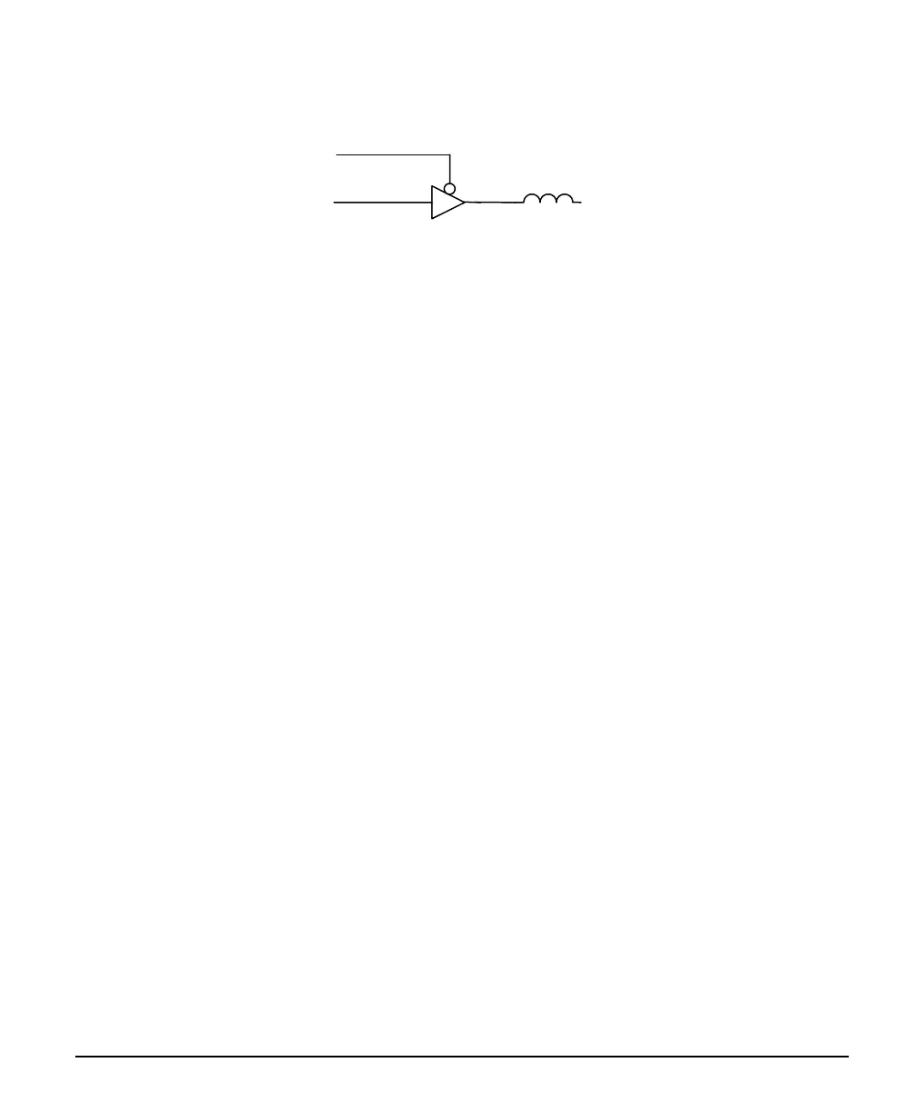
Dual TTL Strobe outputs are provided. The following figure is typical for each strobe out.
FB
Strobe +
Strobe
Strobe EN
• Each strobe output is a tri-state driver, enabled by software.
• Each strobe output is 5V TTL level.
• Each output has a ferrite bead.
• Maximum source current is 32mA typical.
• Maximum sink current is 32mA typical.
• Output switching is < 4.2ns typical.
• Refer to Sapera Strobe Methods parameters:
CORACQ_PRM_STROBE_ENABLE
CORACQ_PRM_STROBE_POLARITY
CORACQ_PRM_STROBE_LEVEL
CORACQ_PRM_STROBE_METHOD
CORACQ_PRM_STROBE_DELAY
CORACQ_PRM_STROBE_DURATION
• See also *.cvi file entries:
Strobe Enable, Strobe Polarity, Strobe Level, Strobe Method, Strobe Delay, Strobe Duration.
Note 6: DC Power Details
• Connect the PC floppy drive power connector to J7 so as to supply DC power to a camera. Both
5Vdc and 12Vdc are available on J4 or on the DB37 External Signals Bracket Assembly.
• Both the 5Volt and 12Volt power pins have a 1.5 amp re-settable fuse on the board. If the fuse is
tripped, turn off the host computer power. When the computer is turned on again, the fuse is
automatically reset.