112 • Appendix: X-I/O Module Option X64 Xcelera-CL PX4 User's Manual
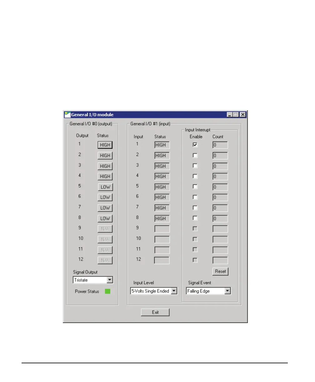
Input Pins: The second section provides input pin status (I/O device #1). Note that this program is a
demo, therefore no action takes place on an input event.
• The first column reads the logic level present on each input. The Input Level drop menu changes
the logic level from 5V TTL to 24V logic. Use the Device Manager program to select the default
logic level type.
• The second column demonstrates activating interrupts on individual inputs. In this demo
program, use the Enable box to activate the interrupt on an input. The Count box will tally
detected input events. Use the Signal Event drop menu to select which input signal edge to
detect. The Reset button clears all event counts.