34
MAGFLO
â
Sensor
To obtain optimum results from the measuring system, the chassis body of the sensor must have
the same electrical potential as the liquid being measured.
5. Installation of sensor
5.1
Potential equalization
(Grounding)
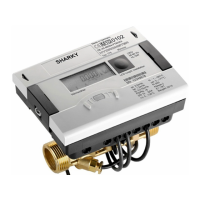
MAG 1100
Graphite gaskets EPDM or PTFE gaskets
Electrically
conductive
piping
A: Potential equalization with electri-
cally conductive graphite gaskets
B: Potential equalization using earth
strap supplied.
C: Potential equalization with electri-
cally conductive graphite gaskets
D: Potential equalization using sepa-
rate potential equalization ring
Electrically
non-conduc-
tive piping
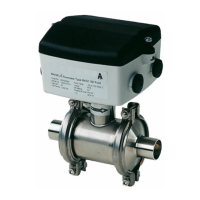
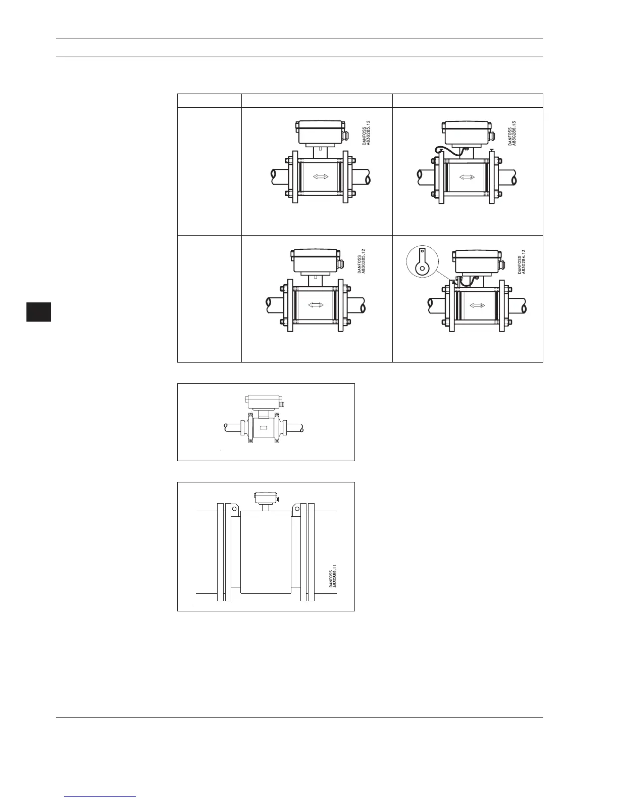
MAG 1100 FOOD
The sensor must be installed between two
adapters. Potential equalization with the liquid
occurs automatically via these adapters and
through the adjacent pipe.
5. Installation of sensor
MAG 3100 W / MAG 3100
(except PTFE liner)
Potential equalization is carried out with the
built-in grounding electrodes. No further action
need to be taken.
 Loading...