41
MAGFLO
â
Installation of signal
conv.
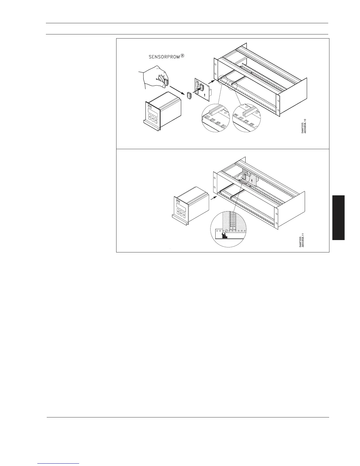
6. Installation of signal converter
6.2.4
Remote installation
Rack mount
(continued from page 38)
Step 1 + 2
Please refer to page 38.
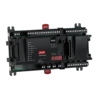
Step 3 (Rack mount units)
Mount the SENSORPROM
®
memory unit on the connection board supplied with the signal
converter as shown. The SENSORPROM
®
unit is supplied with the sensor in the terminal box.
Step 4 (Rack mount units)
Mount the guide rails in the rack system as shown. Distance between guide rails is 4.52 inch.
Guide rails are supplied with the rack system and not with the signal converter.
Step 5 (Rack mount units)
Mount the connection board as shown. Board to be mounted on the inside.
Step 6 (Rack mount units)
Connect the cables as shown under "Electrical connection", section 7.
Step 7 (Rack mount units)
Insert the signal converter into the rack system.
(From sensor terminal box)
 Loading...