48
MAGFLO
â
7. Electrical connection
Elec.con.
7. Electrical connection
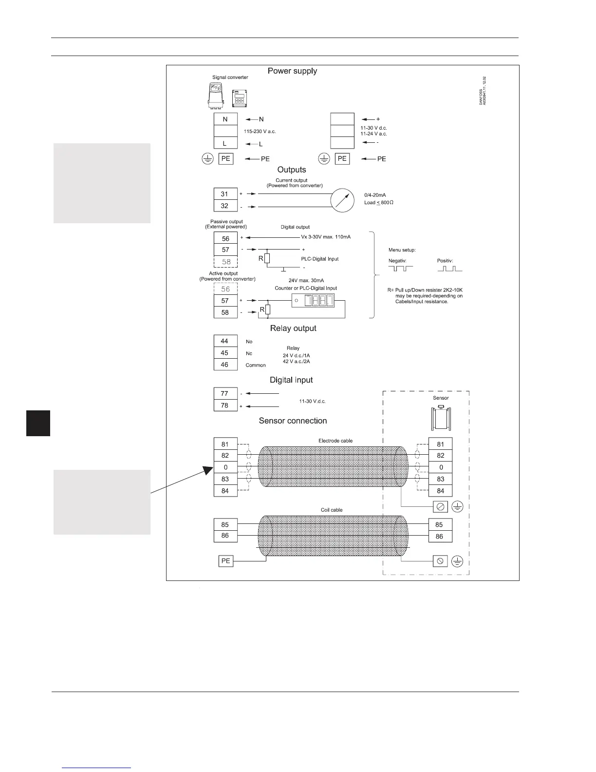
7.1
Signal converter
MAG 5000 and MAG 6000
connection diagram
Grounding
PE must be connected for safety reasons.
Mechanical counters
When connecting a mechanical counter to terminals 57 and 58 (active output), a 1000 mF capacitor
must be connected to the terminals 56 and 58. Capacitor + is connected to terminal 56.
Output cables
When using long cables in an electrically noisy environment we recommend using shielded cable
in metal conduit. See page 15 for max. cable lengths.
Electrode cables
Dotted connections only to be used when using speical cable.
Special cable with indi-
vidual wire shields (shown
with dashed lines) are only
required when using empty
pipe function with low
conductivity process (see
“Specifications, section 2)
Safety Note
Only qualified personnel
should perform wiring or
repairs, and only when the
signal converter is not
powered. Install signal
converter in accordance
with all relevant NEC and
local codes.
 Loading...