38
MAGFLO
â
Installation of signal
conv.
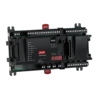
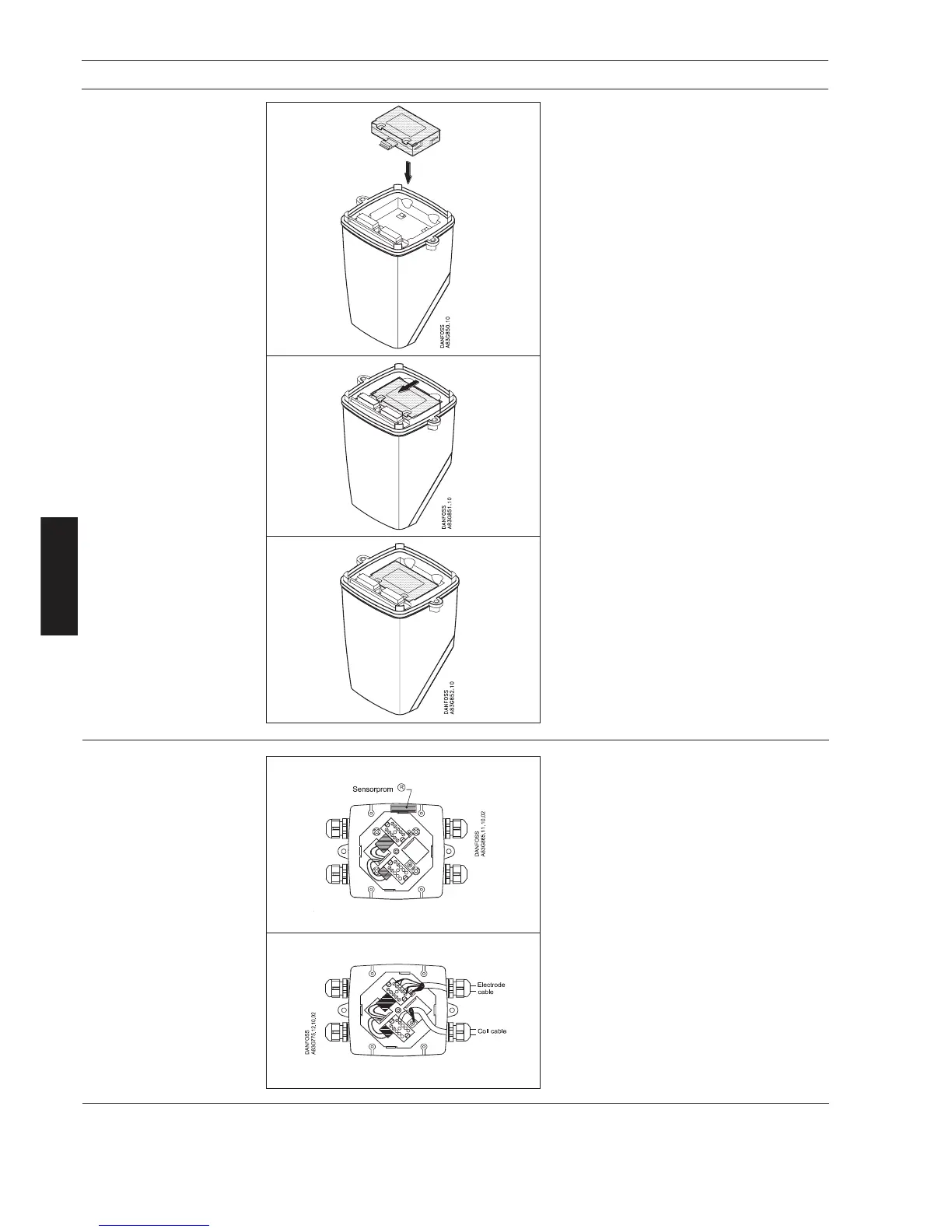
Locate the add-on module in the bottom of the
MAG 6000 signal converter.
6. Installation of signal converter
6.2.1
Add-on modules
(MAG 6000 only)
Press the add-on module forwards as far as
possible.
The add-on module has now been installed
and the signal converter is ready to be
installed on the terminal box.
Communication to the operator menu and
electrically inputs and outputs is automati-
cally established by power on.
Step 2 (All signal converter types)
Fit and connect the electrode and coil cables
as shown in section 7 “Electrical connections”.
The unshielded cable ends must be kept as
short as possible.
The electrode cable and the coil cable must be
two separate cables to prevent interference.
Tighten the cable glands well to obtain opti-
mum sealing.
The two cables can run in the same conduit.
Step 1 (All signal converter types)
Remove the SENSORPROM
®
unit from the
sensor terminal box and mount it under the
connection board for the signal converter
(please refer to the following pages for
specific mounting types).
6.2.2
Remote installation
Sensor end
 Loading...