35
MAGFLO
â
Sensor
5. Installation of sensor
MAG 3100
PTFE liner
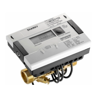
Electrically conductive piping
Use a grounding straps on one side.
Potential equalization, electrically conductive
pipe
Non-conductive piping
Use an grounding ringe. Place the ring between
flowmeter and the adjacent pipe flange.
Selection of grounding ring depends on me-
dium, liner material and application.
Special attention must be given to systems with
cathodic protection.
Integral installation:
The signal converter must be supplied through
an isolation transformer. The terminal "PE" must
never be connected.
Remote installation:
The shield must only be connected at the sen-
sor end via a 1.5 mF capacitor. The shield must
never be connected at both ends.
Isolated sensor:
If above mentioned connections are unaccept-
able, the sensor must be isolated from the pipe
work.
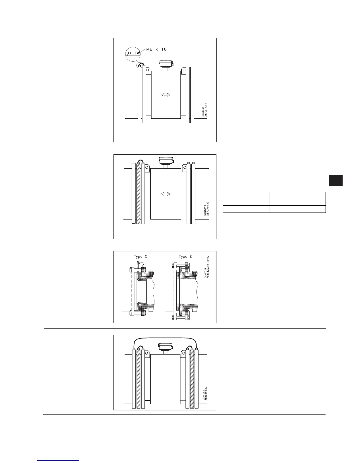
Liner Suitable
material grounding ring
PTFE Type E
Type of grounding flange depending on liner
material
With abrasive liquids, flowmeter inlet protec-
tion may be necessary. Here type C and E
grounding rings are used.
Type C (for all liners except PTFE) is inserted
between the flanges.
Type E (for PTFE liner only) is fitted to the flange.
When using a grounding ring, gaskets must
always be used between the adjacent pipe
flange and the grounding flange.
5.2
Inlet protection MAG 3100
5.3
Cathodic protected piping
 Loading...