49
MAGFLO
â
7. Electrical connection
Elec.con.
7.2
Wiring diagram for signal
converter and sensor
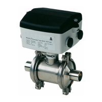
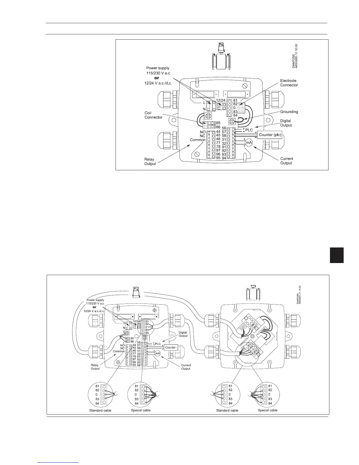
7.2.1 Integral installation
Integral mount
Remote wall mounting
7.2.2
Remote installation wall
mount NEMA 6 enclosure
Cathodic protected piping
Integral mount installation:
The signal converter must be supplied through an isolation transformer. The terminal "PE" must
not be connected.
Sensor cables
· Unshielded cable ends must be as short as possible and the two cables must be kept separate.
Cables must not be spliced.
· Terminals 81 and 84 are only connected when double shielded is used. See 2.7.1.
· Coil cable shield must be connected at both ends. Electrode cable shields must be connected
at sensor side only.
Note
See 5.3 when using cathodic protection.
Note
Mount a grounding wire to the PE on the connnection board to ensure sufficient grounding.
 Loading...