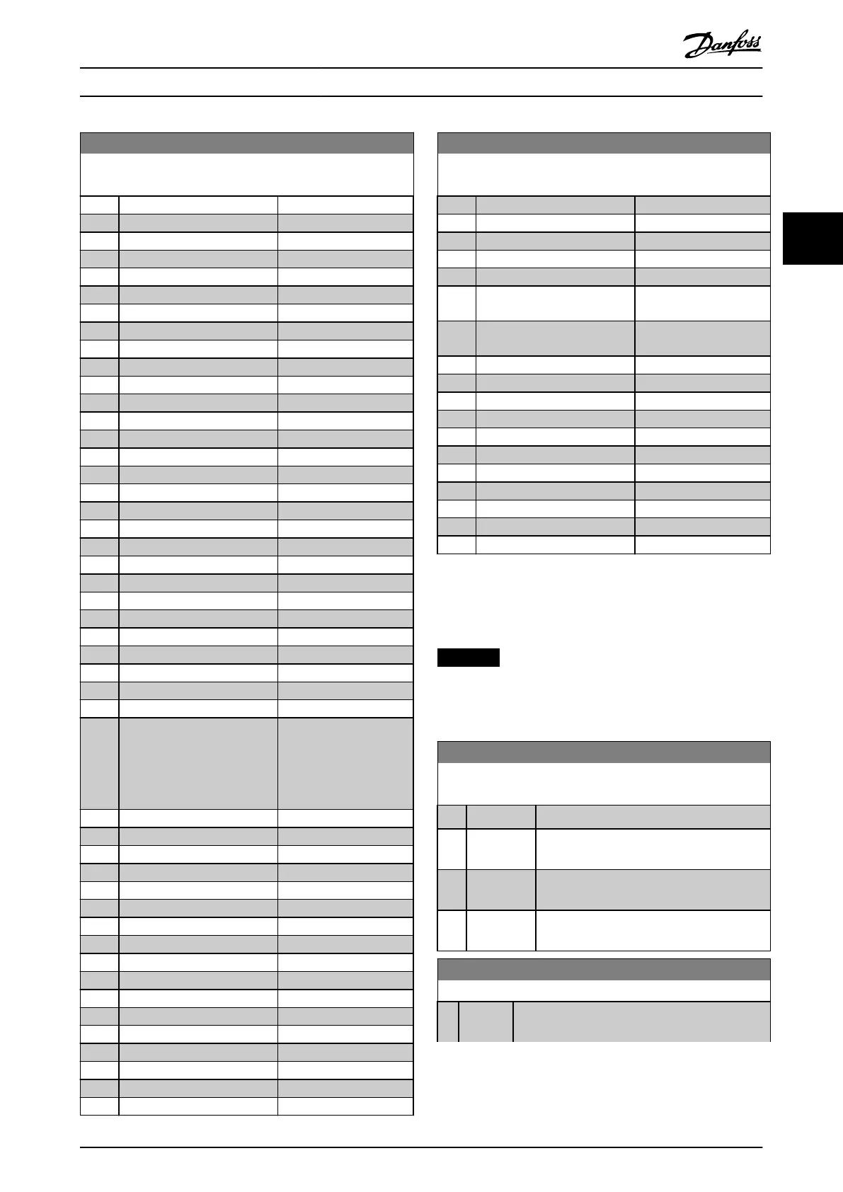
8-43 PCD Read Conguration
Array [64]
Option: Function:
[1646] Motor Phase V Current
[1647] Motor Phase W Current
[1650] External Reference
[1652] Feedback[Unit]
[1653] Digi Pot Reference
[1654] Feedback 1 [Unit]
[1655] Feedback 2 [Unit]
[1656] Feedback 3 [Unit]
[1660] Digital Input
[1661] Terminal 53 Switch Setting
[1662] Analog Input 53
[1663] Terminal 54 Switch Setting
[1664] Analog Input 54
[1665] Analog Output 42 [mA]
[1666] Digital Output [bin]
[1667] Pulse Input #29 [Hz]
[1668] Pulse Input #33 [Hz]
[1669] Pulse Output #27 [Hz]
[1670] Pulse Output #29 [Hz]
[1671] Relay Output [bin]
[1672] Counter A
[1673] Counter B
[1675] Analog In X30/11
[1676] Analog In X30/12
[1677] Analog Out X30/8 [mA]
[1678] Analog Out X45/1 [mA]
[1679] Analog Out X45/3 [mA]
[1684] Comm. Option STW
[1687] Bus Readout Alarm/Warning
[1689] Congurable Alarm/Warning
Word
Shows the alarm/warning
word that is congured
in parameter 8-17 Cong-
urable Alarm and
Warningword.
[1690] Alarm Word
[1691] Alarm Word 2
[1692] Warning Word
[1693] Warning Word 2
[1694] Ext. Status Word
[1695] Ext. Status Word 2
[1696] Maintenance Word
[1697] Alarm Word 3
[1698] Warning Word 3
[1830] Analog Input X42/1
[1831] Analog Input X42/3
[1832] Analog Input X42/5
[1833] Analog Out X42/7 [V]
[1834] Analog Out X42/9 [V]
[1835] Analog Out X42/11 [V]
[1836] Analog Input X48/2 [mA]
[1837] Temp. Input X48/4
8-43 PCD Read Conguration
Array [64]
Option: Function:
[1838] Temp. Input X48/7
[1839] Temp. Input X48/10
[1850] Sensorless Readout [unit]
[1860] Digital Input 2
[2792] % Of Total Capacity
[2795] Advanced Cascade Relay
Output [bin]
[2796] Extended Cascade Relay
Output [bin]
[2969] Flow
[3421] PCD 1 Read from MCO
[3422] PCD 2 Read from MCO
[3423] PCD 3 Read from MCO
[3424] PCD 4 Read from MCO
[3425] PCD 5 Read from MCO
[3426] PCD 6 Read from MCO
[3427] PCD 7 Read from MCO
[3428] PCD 8 Read from MCO
[3429] PCD 9 Read from MCO
[3430] PCD 10 Read from MCO
3.9.5 8-5* Digital/Bus
Parameters for conguring the control word merging.
NOTICE
These parameters are active only when
parameter 8-01 Control Site is set to [0] Digital and control
word.
8-50 Coasting Select
Select the trigger for the coasting function.
Option: Function:
[0] Digital input A digital input triggers the coasting function.
[1] Bus A serial communication port or the eldbus
triggers the coasting function.
[2] Logic AND The eldbus/serial communication port and a
digital input trigger the coasting function.
[3] * Logic OR The eldbus/serial communication port or a
digital input triggers the coasting function.
8-52 DC Brake Select
Option: Function:
Select control of the DC brake via the terminals
(digital input) and/or via the eldbus.
Parameter Description Programming Guide
MG20OB02 Danfoss A/S © 05/2018 All rights reserved. 107
3 3

 Loading...


