22-61 Broken Belt Torque
Range: Function:
10 %* [0 - 100 %] Sets the broken-belt torque as a percentage
of the rated motor torque.
22-62 Broken Belt Delay
Range: Function:
10 s [0 - 600
s]
Sets the time for which the broken belt
conditions must be active before carrying out
the action selected in parameter 22-60 Broken
Belt Function.
3.19.7 22-7* Short Cycle Protection
In some applications, a need for limiting the numbers of
starts often exists. One way to do this is to ensure a
minimum run time (time between a start and a stop) and a
minimum interval between starts.
This means that any normal stop command can be
overridden by parameter 22-77 Minimum Run Time and any
normal start command (start/jog/freeze) can be overridden
by parameter 22-76 Interval between Starts.
None of the 2 functions are active if hand-on mode or
o
mode have been activated via the LCP. If pressing [Hand
On] or [O], the 2 timers are reset to 0 and do not start
counting until [Auto On] is pressed, and an active start
command is applied.
22-75 Short Cycle Protection
Option: Function:
[0] * Disabled Timer set in parameter 22-76 Interval between
Starts is disabled.
[1] Enabled Timer set in parameter 22-76 Interval between
Starts is enabled.
22-76 Interval between Starts
Range: Function:
Size related* [ par. 22-77 -
3600 s]
Sets the minimum time between 2
starts. Any normal start command
(start/jog/freeze) is disregarded
until the timer has expired.
22-77 Minimum Run Time
Range: Function:
0 s* [ 0 - par.
22-76 s]
NOTICE
Does not work in cascade mode.
Sets the minimum run time after a normal start
command (start/jog/freeze). Any normal stop
command is disregarded until the set time has
22-77 Minimum Run Time
Range: Function:
expired. The timer starts counting following a
normal start command (start/jog/freeze).
A coast (inverse) or an external interlock
command overrides the timer.
22-78 Minimum Run Time Override
Option: Function:
[0] * Disabled
[1] Enabled
22-79 Minimum Run Time Override Value
Range: Function:
0 ProcessCtrlUnit* [-999999.999 - 999999.999
ProcessCtrlUnit]
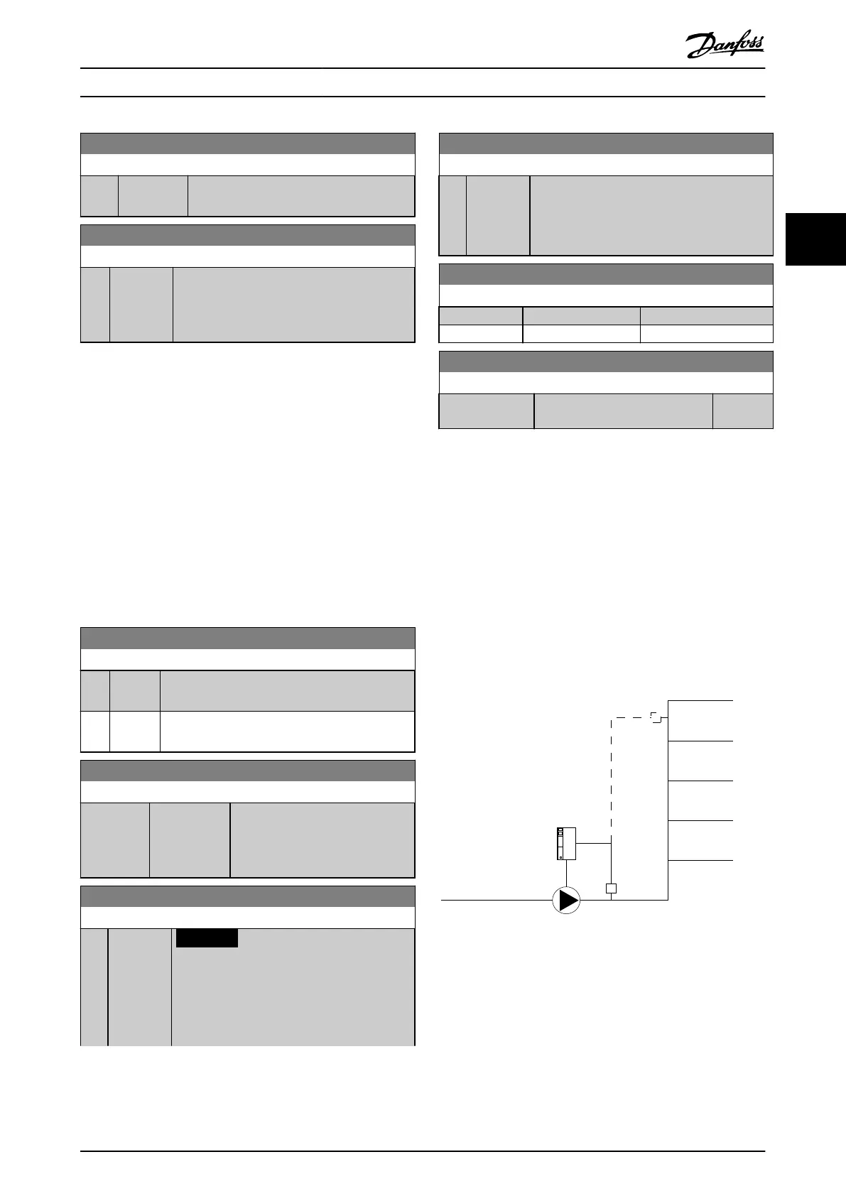
3.19.8 22-8* Flow Compensation
In certain applications, it is not possible for a pressure
transducer to be placed at a remote point in the system,
and it can only be located close to the fan/pump outlet.
Flow compensation operates by adjusting the setpoint
according to the output frequency, which is almost propor-
tional to ow. Thus, it compensates for higher losses at
higher ow rates.
H
DESIGN
(required pressure) is the setpoint for closed-loop
(PI) operation of the frequency converter and is set as for
closed-loop operation without ow compensation.
Illustration 3.70 Flow Compensation Set-up
There are 2 methods which can be employed, depending
on whether the speed at system design working point is
known.
Parameter Description Programming Guide
MG20OB02 Danfoss A/S © 05/2018 All rights reserved. 187
3 3

 Loading...


