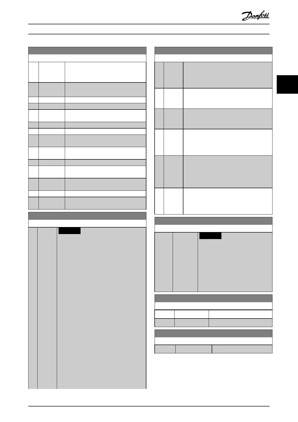
2-13 Brake Power Monitoring
Option: Function:
[2] Trip 120s Trips the frequency converter and shows an
alarm when the calculated power exceeds
100% of the monitoring limit.
[3] Warning &
trip 120s
Activates both of the above, including
warning, trip, and alarm.
[4] Warning 30s
[5] Trip 30s
[6] Warning &
trip 30s
[7] Warning 60s
[8] Trip 60s
[9] Warning &
trip 60s
[10] Warning
300s
[11] Trip 300s
[12] Warning &
trip 300s
[13] Warning
600s
[14] Trip 600s
[15] Warning &
trip 600s
2-15 Brake Check
Option: Function:
NOTICE
Remove a warning arising with [0] O or
[1] Warning by cycling the mains supply.
Correct the fault rst. For [0] O or [1]
Warning, the frequency converter keeps
running even if a fault is found.
Select the type of test and monitoring function
to check the connection to the brake resistor, or
whether a brake resistor is present, and then
show a warning or an alarm if a fault occurs. The
brake resistor disconnection function is tested
during power-up. However, the brake IGBT test is
performed when there is no braking. A warning
or trip disconnects the brake function.
The testing sequence is as follows:
1. Measure the DC-link ripple amplitude
for 300 ms without braking.
2. Measure the DC-link ripple amplitude
for 300 ms with the brake turned on.
3. If the DC-link ripple amplitude while
braking is lower than the DC-link ripple
amplitude before braking +1%, the
brake check fails. If brake check fails, a
warning or alarm is returned.
2-15 Brake Check
Option: Function:
4. If the DC-link ripple amplitude while
braking is higher than the DC-link ripple
amplitude before braking +1%, the
brake check is OK.
[0]
*
O Monitors brake resistor and brake IGBT for a
short circuit during operation. If a short circuit
occurs, a warning appears.
[1] Warning Monitors brake resistor and brake IGBT for a
short circuit and runs a test for brake resistor
disconnection during power-up.
[2] Trip Monitors for a short circuit or disconnection of
the brake resistor, or a short circuit of the brake
IGBT. If a fault occurs, the frequency converter
cuts out while showing an alarm (trip lock).
[3] Stop and
trip
Monitors for a short circuit or disconnection of
the brake resistor, or a short circuit of the brake
IGBT. If a fault occurs, the frequency converter
ramps down to coast and then trips. A trip lock
alarm is shown.
[4] AC brake Monitors for a short circuit or disconnection of
the brake resistor, or a short circuit of the brake
IGBT. If a fault occurs, the frequency converter
performs a controlled ramp down.
2-16 AC brake Max. Current
Range: Function:
100.0 %* [0.0 -
1000.0 %]
NOTICE
Parameter 2-16 AC brake Max.
Current is not eective when
parameter 1-10 Motor Construction
= [1] PM, non-salient SPM.
Enter the maximum allowed current
when using AC braking to avoid
overheating of motor windings.
2-17 Over-voltage Control
Option: Function:
[0] Disabled No OVC required.
[2] * Enabled Activates OVC.
2-19 Over-voltage Gain
Range: Function:
100 %* [10 - 200 %] Select overvoltage gain.
Parameter Description Programming Guide
MG20OB02 Danfoss A/S © 05/2018 All rights reserved. 65
3 3

 Loading...


