ALTERNATIVE CONNECTIONS FOR SERIAL MODELS
ID-NET NETWORK TERMINATION
The network must be properly terminated by a 120 Ohm resistor at the first and last reader of
the network.
INPUTS
There are two optocoupled polarity insensitive inputs available on the 25-pin D-sub
connector of the reader: Input 1 (External Trigger) and Input 2, a generic input.
The electrical features of both inputs are:
The relative pins on the 25-pin D-sub connector are:
Power Supply input voltage +
External Trigger A (polarity insensitive)
External Trigger B (polarity insensitive)
Input 2 A (polarity insensitive)
Input 2 B (polarity insensitive)
Power Supply input voltage -
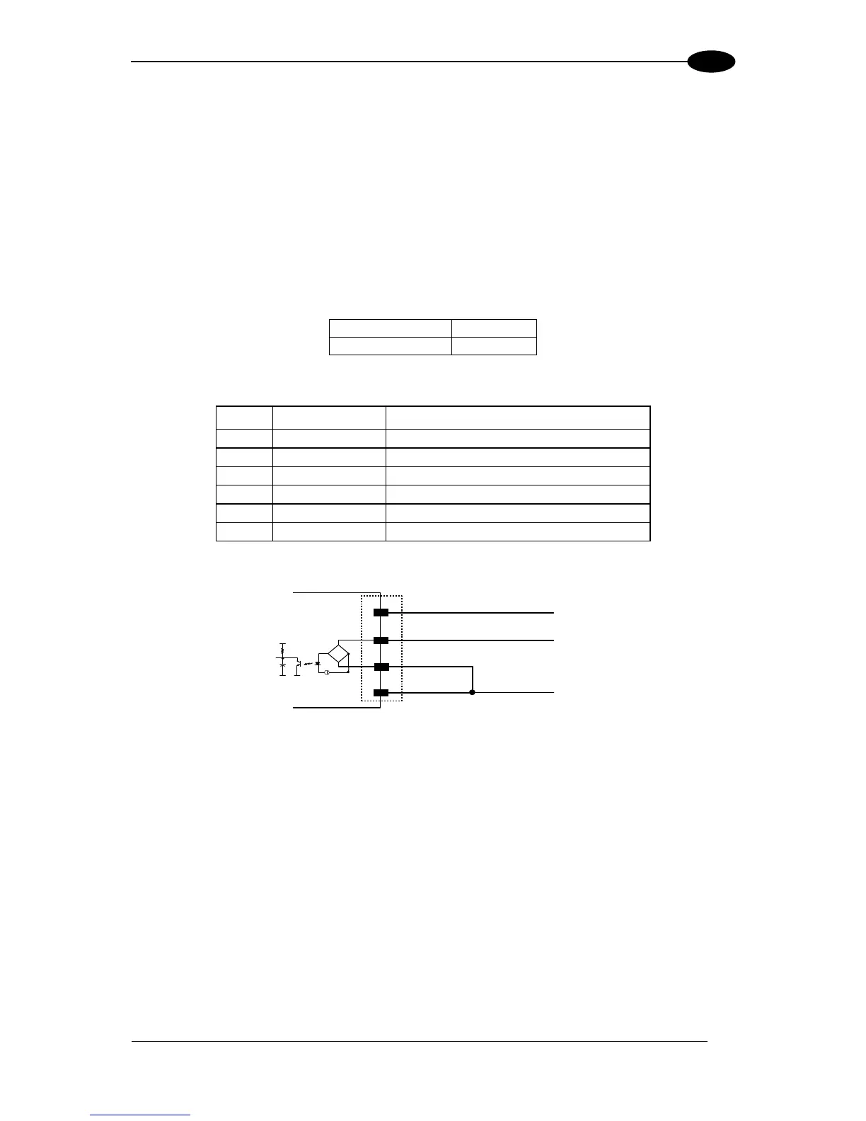
Figure 77 – MEP-593 PNP Photocell Connections Using Scanner Power

 Loading...