ALTERNATIVE CONNECTIONS FOR ETHERNET MODELS
ON-BOARD ETHERNET CONNECTOR
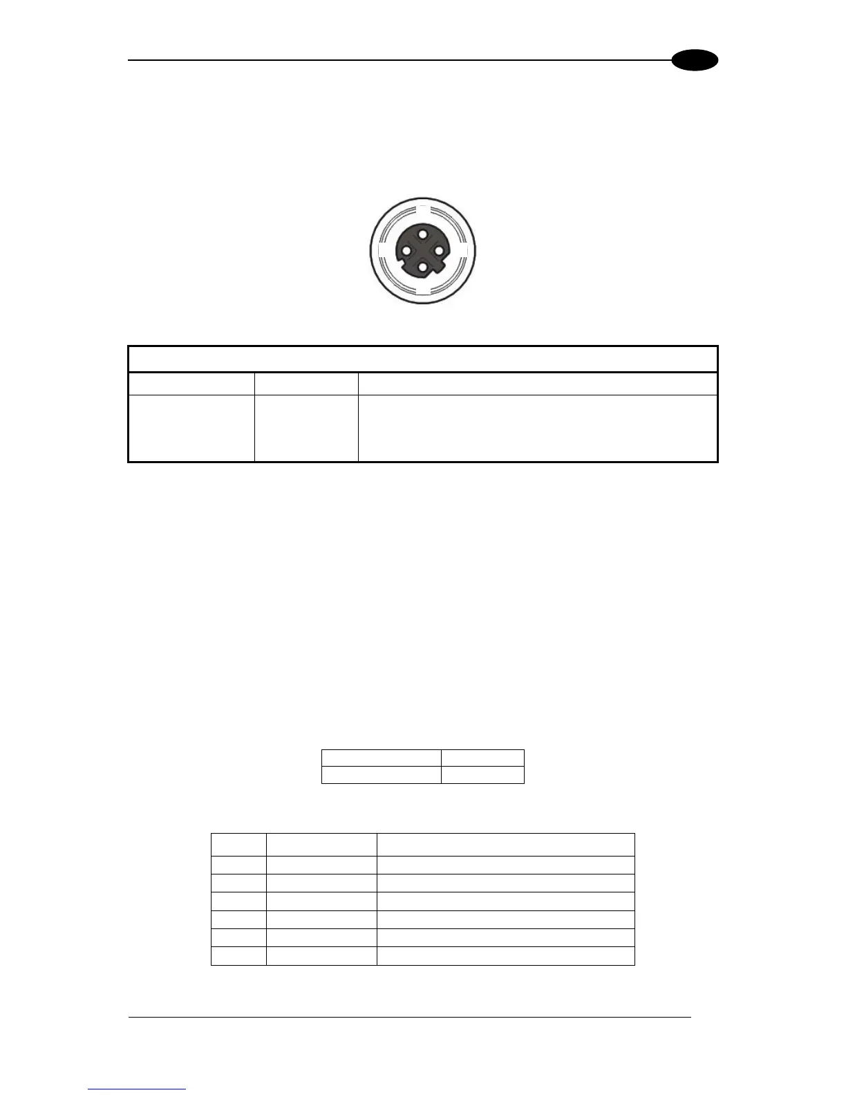
A Standard M12 D-Coded female connector is provided for the on-board Ethernet
connection. This interface is IEEE 802.3 10 BaseT and IEEE 802.3u 100 BaseTx compliant.
Use Cat 5e or superior cables.
Figure 82 - M12 D-Coded Female Ethernet Network Connector
On-Board Ethernet Network Connector Pinout
ID-NET NETWORK TERMINATION
The network must be properly terminated by a 120 Ohm resistor at the first and last reader of
the network.
INPUTS
There are two optocoupled polarity insensitive inputs available on the M12 17-pin connector
of the reader: Input 1 (External Trigger) and Input 2, a generic input.
The electrical features of both inputs are:
The relative pins on the M12 17-pin connector are:
Power Supply input voltage +
External Trigger A (polarity insensitive)
External Trigger B (polarity insensitive)
Input 2 A (polarity insensitive)
Input 2 B (polarity insensitive)
Power Supply input voltage -

 Loading...