4 ELECTRICAL INSTALLATION
Serial Interface models are equipped with a cable terminated by a 25-pin male D-sub
connector for connection to the power supply and input/output signals. For Ethernet models,
an accessory 17-pin to 25-pin cable is available for CBX connections.
We recommend making system connections through one of the CBX connection boxes since
they offer the advantages of easy connection, easy device replacement and filtered
reference signals.
NOTE: If you require direct wiring to the scanner, the details of the connector
pins and relative connections are indicated in Appendix A for Serial models or
in Appendix B for Built-in Ethernet models.
NOTE: Profinet-IO models do not connect to the CBX connection boxes. The
details of the connector pins and relative connections are indicated in
Appendix C.
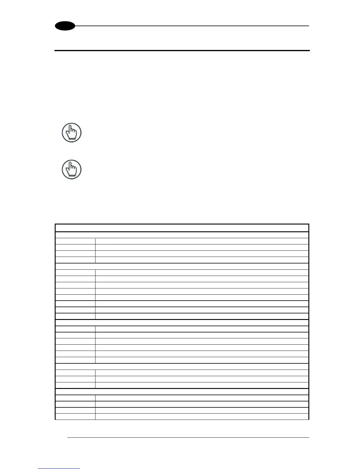
The table below gives the pinout of the CBX100/500 terminal block connectors. Use this
pinout when the DS5100 reader is connected by means of the CBX100/500:
CBX100/500 Terminal Block Connectors
Power Supply Input Voltage +
Power Supply Input Voltage -
Power Source – External Trigger
External Trigger A (polarity insensitive)
External Trigger B (polarity insensitive)
Power Reference – External Trigger
Input 2 A (polarity insensitive)
Input 2 B (polarity insensitive)
Power Reference - Outputs
Auxiliary Interface Reference

 Loading...