4.3.3 ID-NET Network Termination
The network must be properly terminated in the first and last scanner of the network. This is
done by setting the ID-NET Termination Resistance Switch in the CBX100/500 to ON.
4.4 AUXILIARY RS232 INTERFACE
The auxiliary serial interface is used exclusively for RS232 point-to-point connections.
The parameters relative to the aux interface (baud rate, data bits, etc.) as well as particular
communication modes such as LOCAL ECHO can be defined using the Genius utility
program or Genius-based Host Mode Programming provided on the downloadable Genius
mini-DVD zip file.
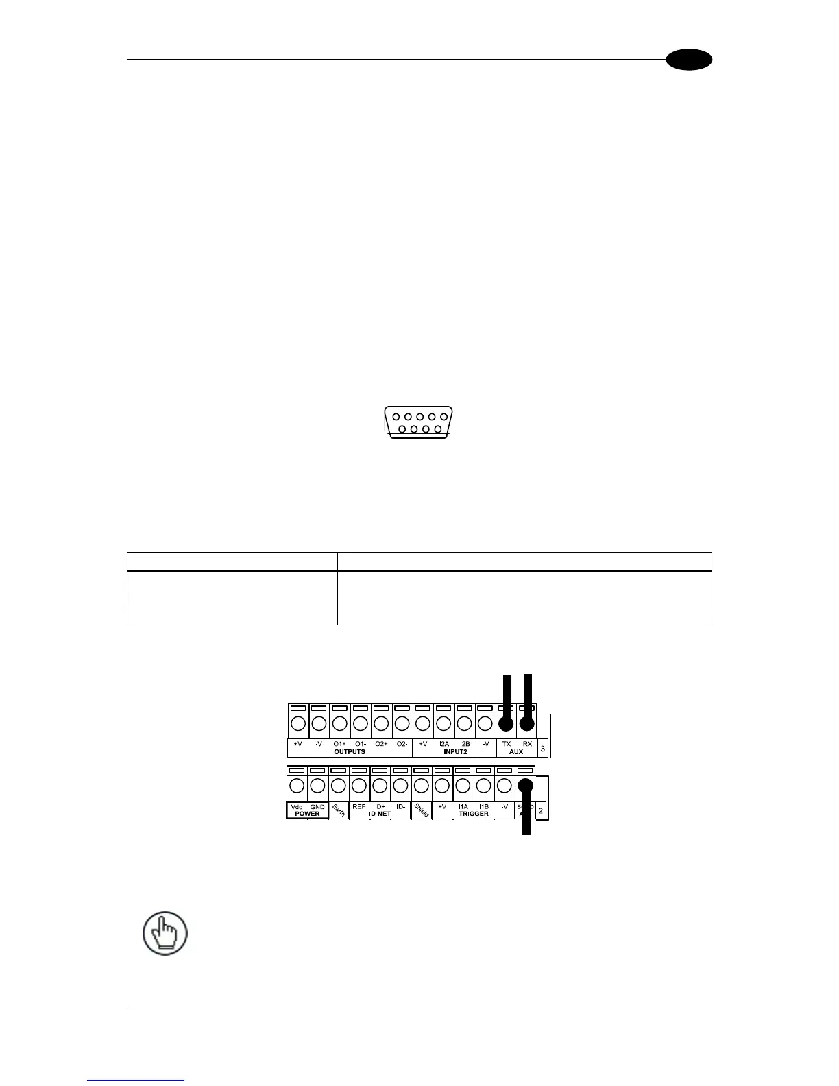
The 9-pin female Auxiliary Interface connector inside the CBX is the preferred connector for
device configuration or communication monitoring.
Figure 41 - 9-pin female connector
If permanent system wiring is required, the following pins are used to connect the RS232
auxiliary interface:
NOTE: Do not connect the Aux Interface to the CBX spring clamp connectors
and the 9-pin connector simultaneously.

 Loading...