NOTE: This chapter illustrates a Stand Alone application. For other types of
installations, such as ID-NET, Fieldbus, Pass-Through layouts, etc., refer to
chapters 4, and 5. For complete scanner configuration using the Genius
configuration program, refer to the Context-Sensitive Help On-Line.
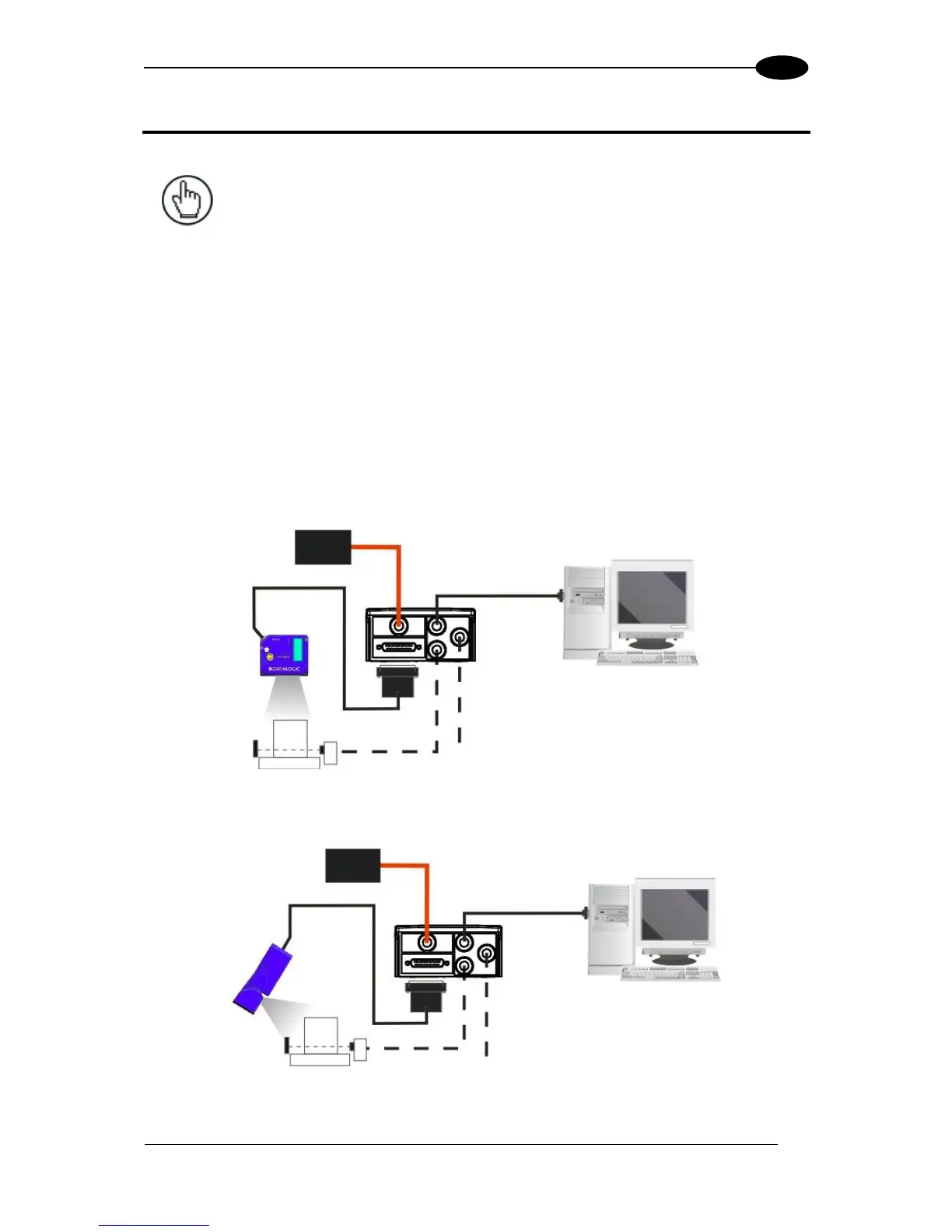
STEP 1 – CONNECT THE SYSTEM
To connect the system in a Stand Alone configuration, you need the hardware indicated in
Figure 1.
In this layout the data is transmitted to the Host on the main serial interface.
In Local Echo communication mode, the RS232 auxiliary interface can be used to transmit
data independently from the main interface selection.
When On-Line Operating mode is used, the scanner is activated by an External Trigger
(photoelectric sensor) when the object enters its reading zone.
Figure 1 – Scanner Connected to a Serial Host in a Stand Alone Layout
Figure 2 – OM Model Scanner Connected to a Serial Host in a Stand Alone Layout

 Loading...