Do you have a question about the Defi ADVANCE FD and is the answer not in the manual?
| Brand | Defi |
|---|---|
| Model | ADVANCE FD |
| Category | Control Unit |
| Language | English |
Safety precautions for installation personnel before handling the product.
Safety guidelines for product installation and operation for customers and personnel.
Check the contents of the package upon receiving the product.
Procedure for installing the ADVANCE Control Unit and associated sensors.
Instructions for configuring system settings such as units, pulses, and cylinders.
Mode for setting various display parameters, including REV BAR, TURBO BAR, and indicators.
Details on real-time, peak, record, playback, and warm-up operational modes.
Setting up custom warning values, conditions, and output configurations.
Information regarding the product warranty card and the limited one-year warranty period.
Guidelines for product inspection and repair services.
Required information for contacting support representatives for inspection or assistance.
Details of the limited warranty, including exclusions and limitations.
Exclusions of liability for damages, including special, incidental, or consequential.
Conditions under which the product warranty becomes void.
Strict prohibition of product modification and its consequences.
User's agreement to protect and release the manufacturer from liabilities.
Explanation of hazard levels (Danger, Warning, Caution) and safety symbols.
Critical dangers and precautions during product installation and handling.
Important warnings and cautions to prevent damage or injury during installation and use.
General do's and don'ts for product handling and installation.
Key confirmation steps after installation and handling.
Warnings related to operating the product while driving or in faulty conditions.
Cautions regarding connector handling and potential damages.
Confirmation points regarding system compatibility and product behavior.
Configurable display patterns, items, and sizes for enhanced user experience.
Setting and managing warnings with visual/audible alerts and sequential indicators.
Features for recording driving data, warm-up, and special display modes.
Inclusion of odometer, trip meter, and extended temperature display ranges.
Graphic animation displayed during idling in special mode.
Technical specifications for power supply, temperature, and humidity ranges.
Specifications for applicable speed pulses and number of engine cylinders.
List of displayable items with their respective ranges and formats.
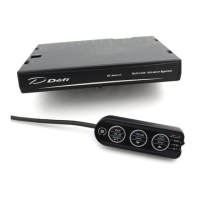
Components of the FD unit, including signal and meter wires.
Various installation hardware like tape, bolts, brackets, and connectors.
List of optional sensor sets and their part numbers for expanded functionality.
List of common repair parts and their respective part numbers.
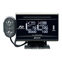
Detailed dimensions and physical features of the FD unit.
Information on the sequential indicator and connector locations.
Dimensions and button layout of the switch unit.
Diagram showing connections between the Control Unit, sensors, and gauges.
Information on the maximum number of gauges and restrictions on connecting similar types.
Detailed steps for wiring the speed and tachometer signal wires.
Important cautions for ensuring safe and correct wiring of signal wires.
Steps for mounting the FD unit and attaching the switch bracket.
Procedure for cutting and attaching buffers to the FD unit backside.
Connecting the switch wire to the correct connector on the FD unit.
Connecting the meter wire to the designated connector on the FD unit.
Securing the FD unit using the brace and knob.
Confirming secure mounting and final checks with the Control Unit manual.
Steps for turning on, confirming modes, and checking for errors.
Setting speed pulse, cylinders, response, display items, and warning values.
Details of the switches and buttons on the ADVANCE FD operation unit.
Details of the switches and buttons on the ADVANCE Control Unit.
Configuring measurement units for speed, pressure, and temperature.
Setting the number of speed pulses per revolution for accurate speed measurement.
Configuring the number of engine cylinders for accurate tachometer readings.
Adjusting the tachometer's response speed (HIGH, MID, LOW).
Selecting automatic or manual control for display brightness.
Enabling or disabling the special display mode based on vehicle speed.
Configuring warm-up display for water or oil temperature.
Designating an active display for ambient brightness sensing.
Performing system setup exclusively on the active display unit.
Setting the minimum and maximum scale values for the REV BAR.
Adjusting the maximum display scale for the revolution bar.
Setting the maximum scale value for the turbo/manifold pressure bar.
Configuring pattern, step, and ON/OFF for sequential indicator lighting.
Setting the threshold for oil pressure warnings.
Configuring whether the warning buzzer is turned on or off.
Assigning unique display numbers to avoid conflicts in multi-unit systems.
Barcodes linking to manual data on the Defi website.
Selecting from four different gauge modes (layouts).
Customizing the multi-display zone for dynamic content.
Selecting between Type A and Type B for product startup and shutdown animations.
Procedure for changing the opening/ending mode via dip switch on Control Unit.
Adjusting the display brightness manually or automatically.
Displaying vehicle information in real-time across different gauge layouts.
How the display indicates warnings with color changes and indicators.
Displaying differential pressure when specific sensors are installed.
Visual indication of engine warm-up status based on temperature settings.
Display showing odometer, trip meter, and idling time under specific conditions.
Displaying maximum values recorded during driving and idling.
Recording driving data for up to 3 minutes.
Playing back recorded driving data with pause and seek functions.
Displaying maximum values from recorded data during playback.
Table of default warning settings for various gauges.
Procedure for adjusting warning thresholds for various gauges.
Configuring the output of warning signals to master warning and indicators.
How sensor errors like open or short circuits are displayed.
Indication of lost communication between the FD and the control unit.
Details on selecting pattern, step, and ON/OFF for sequential indicator LEDs.
Troubleshooting steps for power supply, wiring, and connector issues.
Steps for resolving displayed errors like SHORT or OPEN circuits.
Resolving communication errors between FD and control unit.
Troubleshooting incorrect RPM or speed readings and settings.
Instructions regarding the product tracing label.
Guidelines for disposing of the product in accordance with local regulations.