Hardware Overview 99
System LEDs
The system LEDs for the PowerConnect 7000 Series switches are located on
the right side of the front panel. The system LEDs indicate whether the
switch is the stack master and provide information about the status of system
diagnostics, switch temperature and power.
The system LEDs on the front panel of the switch depend on the switch
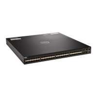
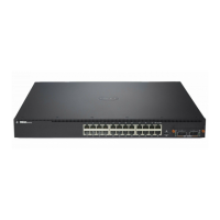
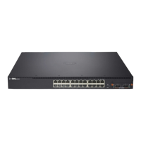
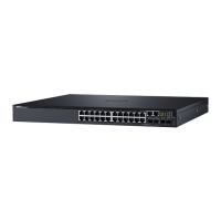
model. Figure 3-14 shows the LEDs available on each model in the
PowerConnect 7000 Series.
Figure 3-14. System LEDs
Table 3-8 contains the System LED definitions.
Table 3-8. System LED Definitions
LED Color Definition
Status Green solid Switch is operating normally.
Green blinking Booting, and the diagnostics test is in progress.
Red solid Critical system error detected.
Red blinking Non-critical system error detected.
FAN Green solid Fans are operating normally.
Red solid One or more fans have failed.
MMPSFan
Stat
u
s
P
WR
MPWR2Fan
S
t
atus
PWR
1
MEPSFan
Status
P
WR
PC7024
PC7024F
PC7048
PC7024P
PC7048P
PC7048R
 Loading...


