Home
Dell
Server
PowerEdge C6220 II
Page 26 (System-Board Assembly Configurations)
Dell PowerEdge C6220 II - System-Board Assembly Configurations
349 pages
Manual
To Next Page
To Next Page
To Previous Page
To Previous Page
Loading...
26
|
About Y
our System
Item
Indicator
, Button
Or Connector
Icon
Description
system using the powe
r button
causes the system to
perform a
graceful shutdown
before power to
the system is turned o
ff.
NOTE:
T
o force
an ungraceful
shutdown, press and hold th
e
power bu
tton for five seconds.
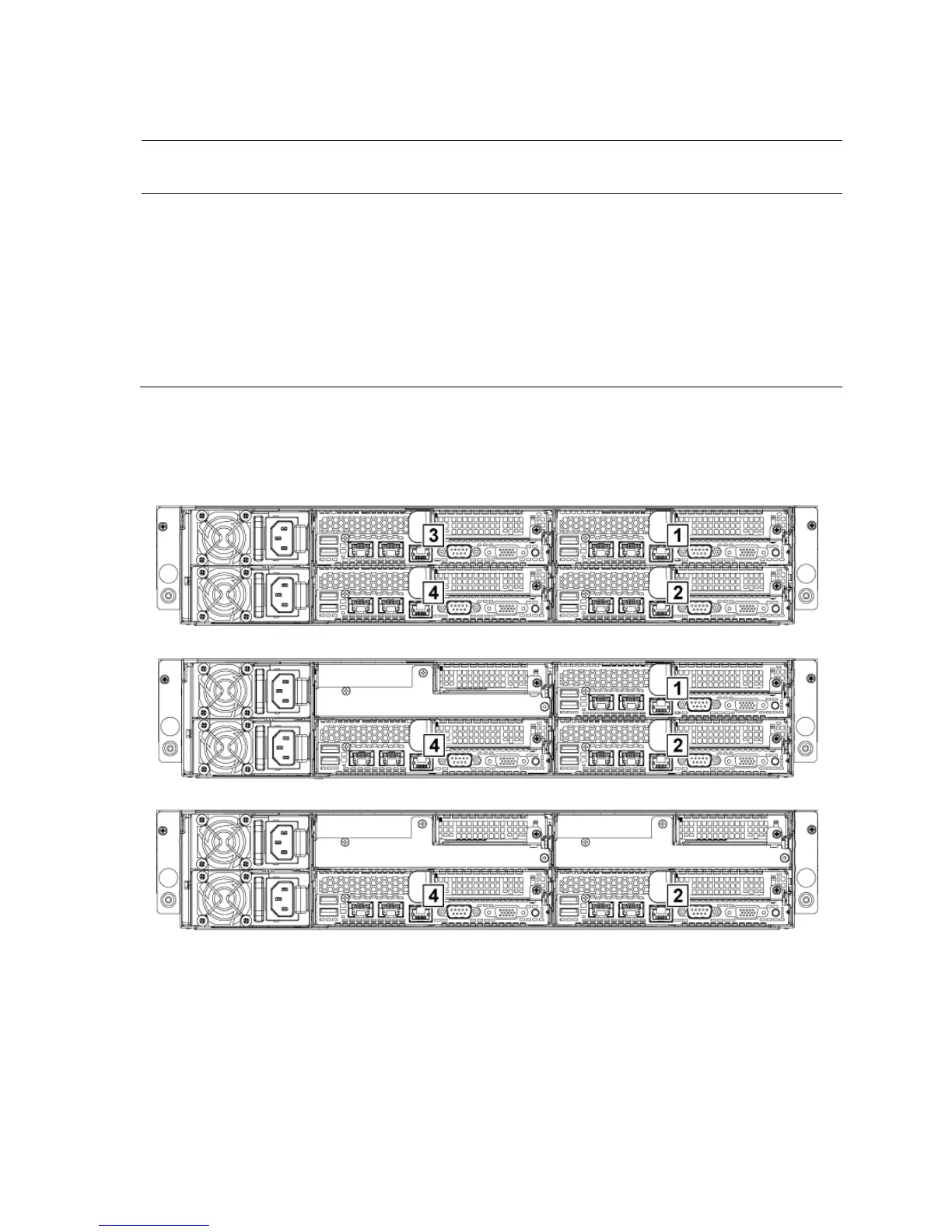
System-Board Ass
embly Configurations
Figure 1-
16
. Enumeration Four System Boards for 1U Node
Figure 1-
17
. Enumeration Three System Boa
rds for 1U Node
Figure 1-
18
. Enumeration T
w
o System Boards for 1U Node
25
27
Table of Contents
Main Page
Default Chapter
3
Table of Contents
3
About Your System
13
Accessing System Features During Startup
13
Front-Panel Features and Indicators
14
Hard-Drive Indicator Patterns
18
Service Tag
21
Back Panel Features and Indicators
24
System-Board Assembly Configurations
26
LAN Indicator Codes
28
Power and System Board Indicator Codes
30
Power Supply Indicator Codes
31
1400W Power Supply
31
1200W Power Supply
32
BMC Heart Beat LED
33
Post Error Code
34
Collecting System Event Log (SEL) for Investigation
34
System Event Log
38
Processor Error
38
Memory ECC
39
PCI-E Error
40
IOH Core Error
41
SB Error
42
POST Start Event
43
POST End Event
44
POST Error Code Event
45
BIOS Recovery Event
45
ME Fail Event
46
SEL Generator ID
46
Sensor Data Record
47
Other Information You May Need
52
C6220 Fresh Air Support
52
C6220 II System Configuration Limitations by Intel Xeon Processor
60
E5-2600 V2 Product Family
60
C6220 II Fresh Air Support
62
Micro SD Card Socket Location
67
Using the System Setup Program
68
Start Menu
68
System Setup Options at Boot
68
Boot Manager
69
Console Redirection
71
Enabling and Configuring Console Redirection
72
Main Menu
76
Main Screen
76
Advanced Menu
78
Power Management
79
Chassis Power Management
80
Configuration Functions
82
CPU Configuration
88
Memory Configuration
94
SATA Configuration
97
PCI Configuration
99
Embedded Network Devices
102
ISCSI Remote Boot
104
Active State Power Management Configuration
105
PCI Slot Configuration
106
USB Configuration
107
Security Menu
108
Server Menu
111
Set BMC LAN Configuration
113
Remote Access Configuration
114
Boot Menu
116
Exit Menu
117
Command Line Interfaces for Setup Options
118
Removing and Installing System Components
150
Safety Instructions
150
Recommended Tools
151
Opening and Closing the System
151
Opening the System
151
Closing the System
152
Inside the System
153
Cooling Fans
154
Removing a Cooling Fan
154
Installing a Cooling Fan
157
Hard Drives
158
Removing a 3.5-Inch Hard-Drive Blank
158
Installing a 3.5-Inch Hard-Drive Blank
158
Removing a 2.5-Inch Hard-Drive Blank
159
Installing a 2.5-Inch Hard-Drive Blank
159
Removing a Hard-Drive Carrier
160
Installing a Hard-Drive Carrier
161
Removing a Hard Drive from a Hard-Drive Carrier
161
Installing a Hard Drive into a Hard-Drive Carrier
163
Installing a 2.5" SSD into a 3.5" Hard-Drive Carrier
163
Power Supplies
166
Removing a Power Supply
166
Installing a Power Supply
167
System-Board Assembly
169
Removing a Dummy System-Board Tray
169
Installing a Dummy System-Board Tray
170
Removing a System-Board Assembly
170
Installing a System-Board Assembly
171
Air Baffle
172
Removing the Air Baffle
172
Installing the Air Baffle
173
Heat Sinks
174
Removing the Heat Sink
174
Installing the Heat Sink
176
Processors
176
Removing a Processor
176
Installing a Processor
178
Interposer Extender for 2U Node
179
Removing the Interposer Extender for 2U Node
179
Installing the Interposer Extender for 2U Node
180
Removing the Interposer Extender Tray for 2U Node
182
Installing the Interposer Extender for 2U Node Tray
183
Expansion-Card Assembly and Expansion Card
184
Removing the Expansion Card for 1U Node
184
Installing the Expansion Card for 1U Node
186
Removing the Expansion Card for 2U Node
187
Installing the Expansion Card for 2U Node
191
PCI-E Slot Priority
193
RAID Card
194
Summary of LSI 9265-8I with RAID Battery, LSI 9210-8I HBA and LSI 9285-8E with RAID Battery
194
LSI 9265-8I Card
195
Removing the LSI 9265-8I Card for 1U Node
195
Installing the LSI 9265-8I Card for 1U Node
198
Cable Routing for LSI 9265-8I Card (1U Node)
199
Removing the LSI 9265-8I Card for 2U Node
202
Installing the LSI 9265-8I Card for 2U Node
206
Cable Routing for LSI 9265-8I Card (2U Node)
207
LSI 9265-8I RAID Battery
210
Removing the LSI 9265-8I RAID Battery Assembly
210
Installing the LSI 9265-8I RAID Battery Assembly
212
Removing the LSI 9265-8I RAID Battery
212
Installing the LSI 9265-8I RAID Battery
213
Riser Card
214
Optional Riser Cards
214
Removing the Riser Card for 1U Node
216
Installing the Riser Card for 1U Node
217
Cable Routing for Riser Card (1U Node)
217
Removing the Riser Card for 2U Node
218
Installing the Riser Card for 2U Node
220
Cable Routing for Riser Card (2U Node)
221
Optional Mezzanine Cards
222
Removing the LSI 2008 SAS Mezzanine Card
222
Installing the LSI 2008 SAS Mezzanine Card
223
Cable Routing for LSI 2008 SAS Mezzanine Card (1U Node)
224
Cable Routing for LSI 2008 SAS Mezzanine Card (2U Node)
225
Removing the 1Gbe Mezzanine Card
229
Installing the 1Gbe Mezzanine Card
231
Removing the 10Gbe Mezzanine Card
232
Installing the 10Gbe Mezzanine Card
235
Mezzanine-Card Bridge Board
236
Removing the Mezzanine-Card Bridge Board
236
Installing the Mezzanine-Card Bridge Board
237
System Memory
238
Memory Slot Features
238
Supported Memory Module Configuration
238
Removing the Memory Modules
240
Installing the Memory Modules
242
System Battery
244
Replacing the System Battery
244
System Board
246
Removing a System Board
246
Installing a System Board
248
Cable Routing for Onboard SATA Cables (1U Node)
249
Cable Routing for Onboard SATA Cables (2U Node with 3.5" Hdds)251
251
Cable Routing for Onboard SATA Cables (2U Node with 2.5" Hdds)253
253
Power Distribution Boards
254
Removing a Power Distribution Board
254
Installing a Power Distribution Board
259
Cable Routing for Power Distribution Board
261
Middle Planes
264
Removing the Middle Planes
264
Installing the Middle Planes
270
Cable Routing for Middle Plane to Direct Hard-Drive Backplane
273
Cable Routing for Middle Plane to 2.5" Hard-Drive Backplane for Expander Configuration
278
Direct Backplanes
280
Removing the Direct Backplane
280
Installing the Direct Backplane
285
2.5-Inch Hard Drive Expander Configuration
287
Removing the 2.5-Inch Hard Drive Backplane for Expander Configuration
287
Installing the 2.5-Inch Hard Drive Backplane for Expander Configuration
295
Front Panels
296
Removing the Front Panel
296
Installing the Front Panel
298
Sensor Boards
300
Removing the Sensor Board for 3.5" Hard-Drive System
300
Installing the Sensor Board for 3.5" Hard-Drive System
301
Cable Routing for Sensor Board and Front Panel for 3.5" Hard Drive System
302
Removing the Sensor Board for 2.5" Hard-Drive System
304
Installing the Sensor Board for 2.5" Hard-Drive System
306
Cable Routing for Sensor Board and Front Panel for 2.5" Hard Drive System
307
Troubleshooting Your System
309
Minimum Configuration to POST
309
Safety First - for You and Your System
309
Installation Problems
310
Troubleshooting System Startup Failure
310
Troubleshooting External Connections
310
Troubleshooting the Video Subsystem
311
Troubleshooting a USB Device
311
Troubleshooting a Serial I/O Device
312
Troubleshooting a NIC
312
Troubleshooting a Wet System
313
Troubleshooting a Damaged System
314
Troubleshooting the System Battery
315
Troubleshooting Power Supplies
316
Troubleshooting System Cooling Problems
316
Troubleshooting a Fan
317
Troubleshooting System Memory
318
Troubleshooting a Hard Drive
320
Troubleshooting a Storage Controller
321
Troubleshooting Expansion Cards
322
Troubleshooting Processors
323
IRQ Assignment Conflicts
324
Jumpers and Connectors
325
C6220 II System Board Connectors
325
C6220 System Board Connectors
326
Backplane Connectors
328
3.5" Hard-Drive Direct Backplane
328
Hard-Drive Direct Backplane
330
2.5" Hard-Drive Expander Backplane
332
Middle Plane Connectors
333
Interposer Extender for 2U Node Connectors
334
LSI 2008 SAS Mezzanine Card Connectors
335
1Gbe Mezzanine Card Connectors
336
10Gbe Mezzanine Card Connectors
337
Power Distribution Board 1 Connectors
338
Power Distribution Board 2 Connectors
339
Sensor Board Connectors
339
Jumper Settings
340
System Configuration Jumper Settings on the C6220 II System Board340
340
System Configuration Jumper Settings on the C6220 System Board341
341
Direct Backplane Jumper Settings
342
Getting Help
343
Contacting Dell
343
Index
344
Other manuals for Dell PowerEdge C6220 II
Hardware Owner's Manual
345 pages
Technical Guide
36 pages
Getting Started
64 pages
Related product manuals
Dell PowerEdge C6220
316 pages
Dell PowerEdge T110 II
142 pages
Dell PowerEdge R210 II
57 pages
Dell PowerEdge C6100
160 pages
Dell PowerEdge C6320
183 pages
Dell PowerEdge C6400
88 pages
Dell PowerEdge C6600
103 pages
Dell EMC PowerEdge C6420
127 pages
Dell EMC PowerEdge C6525
80 pages
Dell EMC PowerEdge C6520
89 pages
Dell PowerEdge C1100
144 pages
Dell PowerEdge
56 pages

 Loading...