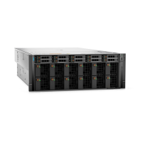
Table 91. Pogo pin cable connection to bezel LED—Rear Accessed configuration
From To
POGO (pogo pin connector) LED BOARD (bezel LED connector)
Figure 72. Pogo pin cable connection to bezel LED and pressure sensor—Front Accessed configuration
Table 92. Pogo pin cable connection to bezel LED—Front Accessed configuration
From To
POGO (pogo pin connector) LED BOARD (bezel LED connector) and PRESSURE SENSOR
(pressure sensor connector)
Figure 73. PERC H965 PA1 NVMe cable connection with 4x 2.5-inch backplane
Table 93. PERC H965 PA1 NVMe cable connection with 4x 2.5-inch backplane
From To
CTRL_SRC_PA1 (PERC connector) BP_DST_PB1 (backplane signal connector) and BP_DST_PA1
(backplane signal connector)
104 Installing and removing system components

 Loading...

