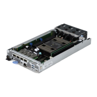
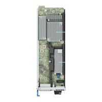
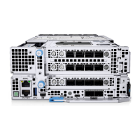
Table 104. System board connectors description(continued)
Item Connector Description
2 25 GbE LOM (4) 25 GbE network connectors
3 POGO connector POGO connector
4 J_LFT_CP1 Left control panel
5 TPM TPM connector
6 PIB_SIG1 Power Interposer Board ( PIB)
connector
7 J_RGT_CP Right control panel
8 RISER1_PWR Riser 1 power connector
9 Coin cell battery Coin cell battery
10 SL7_PCH_SA1 BOSS N1 connector
11 SL6_CPU1_PA4 Riser 1 connector
12 A5, A3, A7, A1 DIMM slots (A5, A3, A7, A1)
13 CPU Processor socket
14 SL5_CPU1_PA3 PCIe cable connector
15 SL4_CPU1_PB3 PCIe cable connector
16 SL3_CPU1_PB2 PCIe cable connector
17 SL2_CPU1_PA2 PCIe cable connector
18 Fan 4 Fan 4 connector
19 Fan 5 Fan 5 connector
20 Fan 6 Fan 6 connector
21 SYS_PWR1 System power connection 1
22 SYS_PWR2 System power connection 2
23 A4, A6, A2, A8 DIMM slots (A4, A6, A2, A8)
24 SL1_CPU1_PA1 Riser 3 connector
System board jumper settings
For information about resetting the password jumper to disable a password, see the Disabling a forgotten password section.
Table 105. System board jumper settings
Jumper Setting Description
PWRD_EN The BIOS password feature is enabled.
The BIOS password feature is disabled. The BIOS password is
now disabled and you are not allowed to set a new password.
NVRAM_CLR The BIOS configuration settings are retained at system boot.
The BIOS configuration settings are cleared at system boot.
168 Jumpers and connectors

 Loading...

