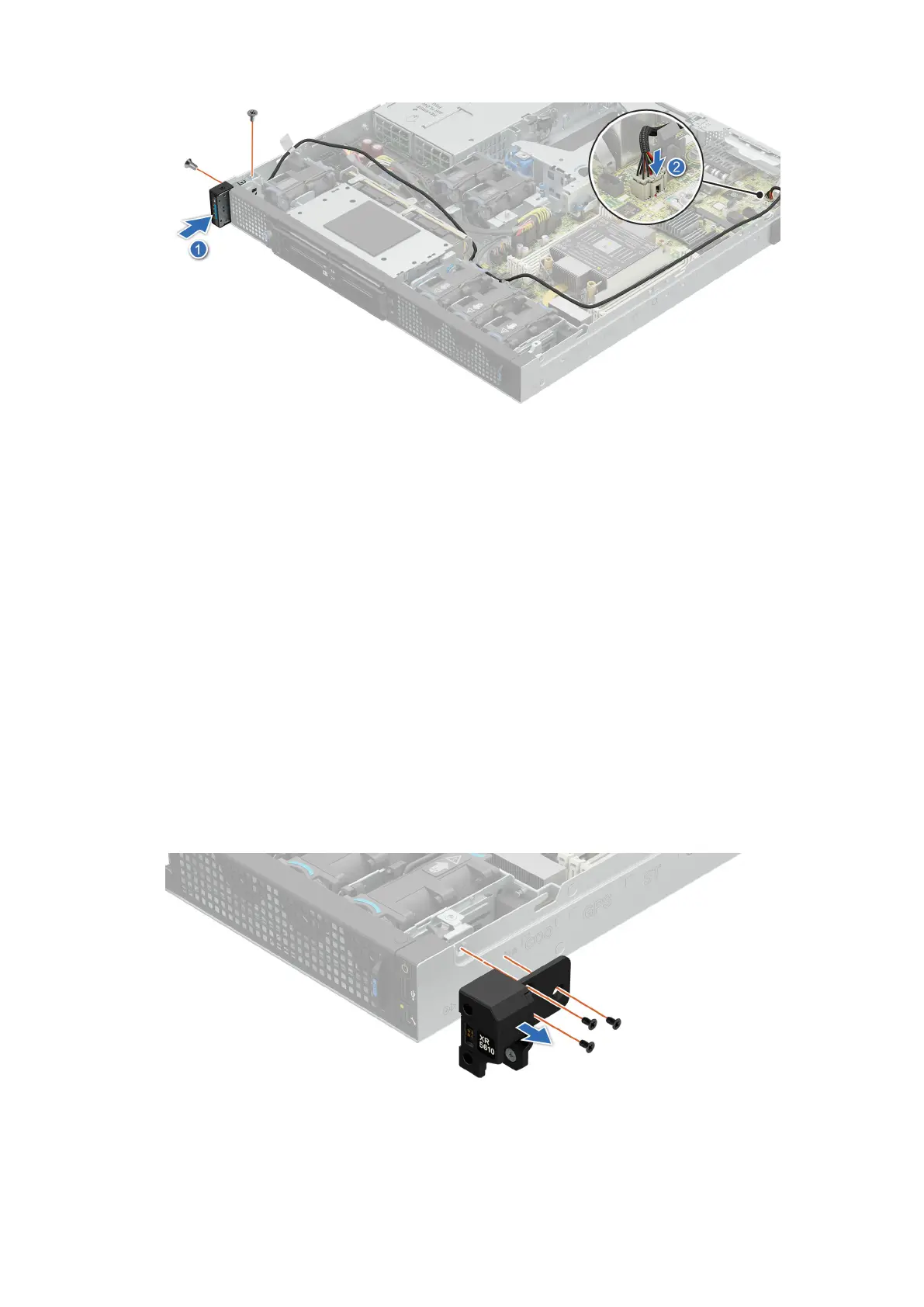
Figure 135. Installing the status LED control panel assembly for Front Accessed configuration
Next steps
1. Install the expansion card riser 1.
2. Install the air shrouds.
3. Follow the procedure listed in the After working inside your system.
Removing the power button control panel for Rear Accessed
configuration
Prerequisites
1. Follow the safety guidelines listed in the Safety instructions.
2. Follow the procedure listed in the Before working inside your system.
3. Remove the processor air shroud.
4. Remove the expansion card riser 1.
Steps
1. Using the Phillips 2 screwdriver, remove the screws that secure the right ear handle.
Figure 136. Removing the right ear handle for Rear Accessed configuration
2. Disconnect the power button control panel cable from the system board connector and remove the cable from cable clip.
160
Installing and removing system components
 Loading...


