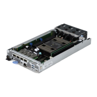
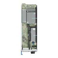
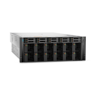
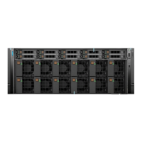
Figure 127. Installing the system board
4. Using a Phillips 2 screwdriver, tighten the screws sequentially and secure the system board to the chassis.
Figure 128. System board screw fastening sequence
Next steps
1. Reconnect all cables to the system board.
NOTE:
Ensure that the cables inside the system are routed along the chassis wall and secured using the cable securing
brackets.
2. Replace the following components:
a. Trusted Platform Module (TPM)
NOTE: The TPM Module must be replaced only while installing a new system board.
b. Processor and heat sink module
c. BOSS N1 card
d. Memory modules
e. OCP riser
f. Reconnect all cables to the system board.
NOTE:
Ensure that the cables inside the system are routed along the chassis wall and secured using the cable
securing brackets.
152 Installing and removing system components

 Loading...

