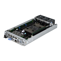
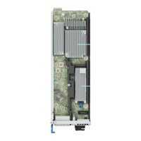
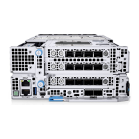
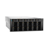
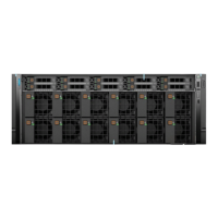
Figure 59. Left ear cable from MIO to left ear—Front and Rear Accessed configuration
Table 79. Right ear cable from MIO to right ear - Front and Rear Accessed configuration
From To
J_LFT_CP1 (left ear connector on system board) LFT_EAR (left ear control panel)
Figure 60. Power Interposer Board (PIB) connection to the system board
Table 80. Power Interposer Board (PIB) connection to the system board
From To
MB_PIB (PIB signal connector) J_PIB_SIG1 (system board connector)
PIB_PWR1 (PIB power connector) SYS_PWR_CONN1 (system board connector)
PIB_PWR2 (PIB power connector) SYS_PWR_CONN2 (system board connector)
98 Installing and removing system components

 Loading...

