Adding and Replacing Parts 207
3
Remove the six rubber screw-covers/display bumpers.
4
Remove the two screw covers and the four shoulder screws.
5
Remove the four M2.5 x 5-mm screws at the corners of the bezel.
NOTICE: Removal of the bezel from the display back cover requires extreme care
to avoid damage to the bezel.
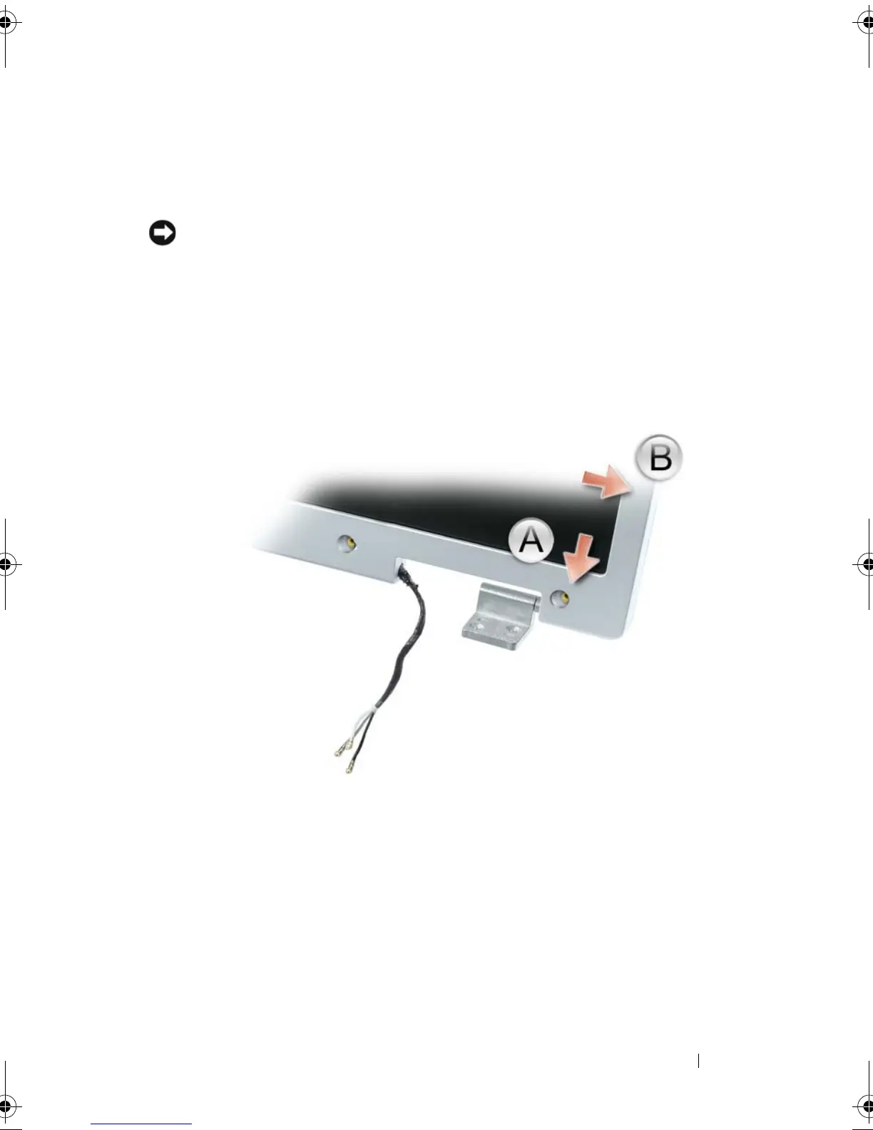
6
Use your fingers to separate the bezel from the display back cover by
pulling the lower-right corner of the bezel down toward the bottom edge
(A) of the display assembly to clear the tab on the bottom of the lower-
right corner. Then pull the bezel toward the right side of the display
assembly to clear the tab on the side (B) of the lower-right corner.
book.book Page 207 Tuesday, August 28, 2007 10:20 AM