ComponentNO. NO.
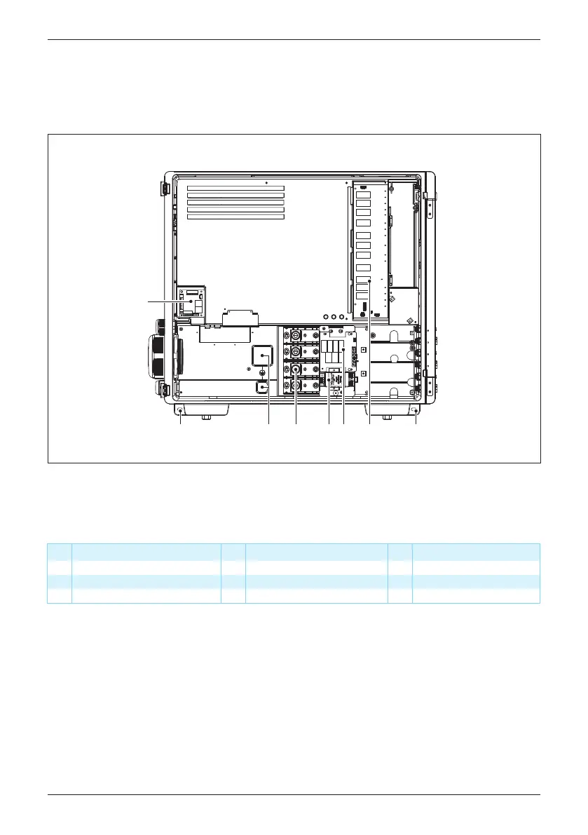
Internal fan 2
AC terminal
Component
6
NO. Component
1 2
7
DC Type II SPD
3
AC Type II SPD 8
Internal fan 1
4
Internal grounding point 5 Rapid Shutdown system
9 External grounding point
Table 2-4: layout description
Figure 2-4: layout
Communication module
①
②
③
⑤ ⑥ ⑦④⑨ ⑨⑧
Figure 2-4 illustrate the general layout of the inverter
chassis and wiring area.
The wiring area includes terminals for connection of the output (AC) wiring,
surge protection devices (SPD).
16
Introduction