3.7.1 RS-485 Connection3.7.1 RS-485 Connection
The pin definition for the RS-485 terminal block is shown in Table 3-7.
- Pins 1 and 2 provide a 12VDC / 0.5A bus for use with accessories.
- Pins 3 and 5 are both connected to the DATA+ input.
- Pins 4 and 6 are both connected to the DATA- input.
These connections allow easy daisy-chaining of multiple inverters.
A 120ohm bus termination resistor and associated control switch are located
on the communication board (
Table 3-8
).
Different RS-485 connection scenarios require different set up for the 120ohm
bus termination resistor.
•
When several inverters are cascaded (i.e., "daisy-chained") only the last inverter
in the chain must have its bus termination resistor switched ON (Figure 3-23).
• The length of RS-485 cable is recommended to be less than 30m in general.
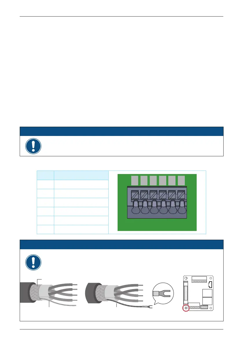
Table 3-7: RS-485 Terminal block wiring
- In order to have good transfer quality, twisted-pair wire is recommended to be
used as communication cable.
ATTENTION
INFORMATION
* Screw torque: 0.59 N•m
(cross-section: 0.5~1.5 mm²)
strip from shielding layer
shielding layer
Insulation Tape
When the RS-485 cable needs to be grounded, please follow the steps below.
1. strip a wire from the shielding layer and properly insulate it
2. crimp the insulated wire to the Y-type lug and fix it in position A
SNYBL1-4
A
Pin Function
1 VCC (+12V)
2 GND (It is NOT the PE)
3 DATA+
4 DATA-
5 DATA+
6 DATA-
1 2 3 4 5 6
VCC GND D+ D- D+ D-
44
Installation