3.4.6 AC Wiring of M100A_280
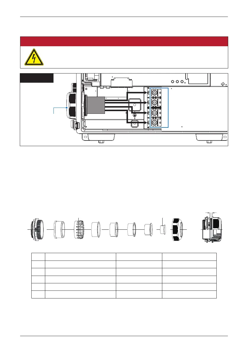
Figure 3-15: Location for AC terminal of M100A_280
(1) Ensure the AC disconnect device is in “OFF”
(2) Strip off the insulation of each cable by 30mm.
(3) For the aluminum conductor, remove the oxide film of the conductor surface
and apply the protective grease.
(4) Please refer to
Table 3-5 to choose proper inner rubber of cable gland.
Improper cable or rubber cannot provide exact waterproof performance and
will lead to water intrusion to damage inverter.
DANGER : ELECTRICAL HAZARD!!
- Always no energy on the AC power cables during the cable installation to
prevent electrical hazard.
AC entry -
33 mm
trade size
gland
L1
L2
L3
N
After inserting conductor,
torque terminal nut
by 42.4 N•m
(5) Tighten all screws of the terminal with 42.4 N-m torque.
(6) Fasten all AC cable glands for sealing.
M100A_280
1 2 3 4 5
seal
plug
clamping
claw
P
1
2
3
4
5
72 - 77 mm 6.5 - 4.5 mm
6 - 3 mm
5.5 - 2 mm
5.5 - 0 mm
4.5 - 0 mm
65 - 72 mm
57 - 65 mm
45 - 57 mm
33 - 45 mm
Cable diameter range
Torque
10
N•m
12 N•m
15 N•m
15 N•m
15 - 20 N•m
Dimension of P
Table 3-5: Specification of M100A_280 AC gland
34
Installation