Advanced application features I/O line monitoring
XBee®-PRO 900HP/XSC RF Modules
169
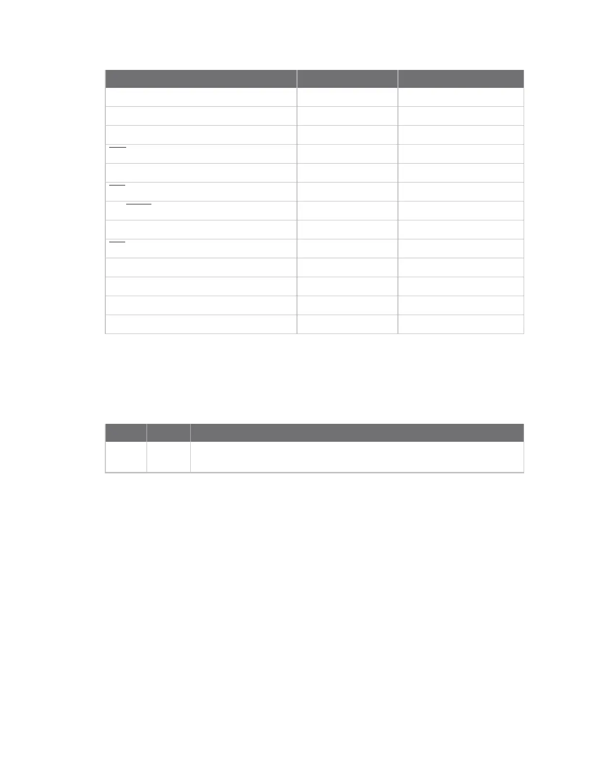
Device pin name Device pin number Configuration command
CD / DIO12 4
P2
PWM0 / RSSI / DIO10 6
P0
PWM1 / DIO11 7
P1
DTR
/ SLEEP_RQ / DIO8 9
D8
AD4 / DIO4 11
D4
CTS
/ DIO7 12
D7
ON/
SLEEP
/ DIO9 13
D9
ASSOC / AD5 / DIO5 15
D5
RTS
/ DIO6 16
D6
AD3 / DIO3 17
D3
AD2 / DIO2 18
D2
AD1 / DIO1 19
D1
AD0 / DIO0 / Commissioning Pushbutton 20
D0
Use the PR command to enable internal pull up/down resistors for each digital input. Use the PD
command to determine the direction of the internal pull up/down resistor.
If you issue the IS command using a a local or remote AT Command API frame, then the device returns
an AT Command Response (0x88) frame with the I/O data included in the command data portion of
the packet.
Field Name Description
1 Sample
sets
Number of sample sets in the packet. Always set to 1.