Operation Basic operational design
XBee®-PRO 900HP/XSC RF Modules
35
Basic operational design
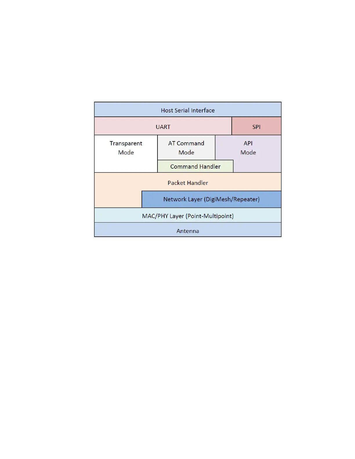
The XBee-PRO 900HP RF ModuleRF Module uses a multi-layered firmware base to order the flow of
data, dependent on the hardware and software configuration that you choose. The following graphic
shows a configuration block diagram, with the host serial interface as the physical starting point and
the antenna as the physical endpoint for the transferred data. As long as one block can touch another
block, the two interfaces can interact. For example, if the device is using SPI mode, Transparent Mode
is not available.
The command handler is the code that processes commands from AT Command Mode or Application
Programming Interface (API) Mode (see AT commands). The command handler also processes
commands from remote radios (see Remote AT commands).
Serial interface
The XBee-PRO 900HP RF Module interfaces to a host device through a serial port. The device can
communicate through its serial port with the following:
n Logic and voltage compatible universal asynchronous receiver/transmitter (UART).
n Level translator to any serial device, for example, through an RS-232 or USB interface board.
n SPI, as described in SPI communications.
UART data flow
Devices that have a UART interface connect directly to the pins of the XBee-PRO 900HP RF Module as
shown in the following figure. The figure shows system data flow in a UART-interfaced environment.
Low-asserted signals have a horizontal line over the signal name.