Hardware Pin signals
XBee®-PRO 900HP/XSC RF Modules
24
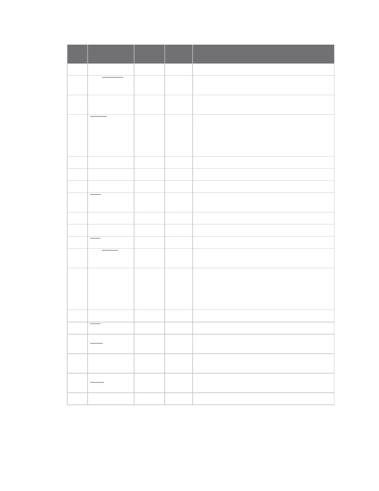
Pin # Name Direction
Default
state Description
2 DOUT/DIO13 Both Output GPIO/UART data out
3 DIN/CONFIG
/DIO14
Both Input GPIO/UART data in
4 DIO12/SPI_
MISO
Both Output GPIO/SPI slave out
5 RESET Input Device reset. Drive low to reset the device. This is
also an output with an open drain configuration
with an internal 20 kΩ pull-up (never drive to logic
high, as the device may be driving it low). The
minimum pulse width is 1 mS.
6 DIO10/PWM0 Both GPIO/RX signal strength indicator
7 DIO11/PWM1 Both GPIO/pulse width modulator
8 Reserved Disabled Do not connect
9 DTR/SLEEP_
RQ/DIO8
Both Input GPIO/pin sleep control line (DTR on the
development board)
10 GND Ground
11 DIO4/SPI_MOSI Both GPIO/SPI slave in
12 CTS/DIO7 Both Output GPIO/clear-to-send flow control
13 ON_SLEEP
/DIO9
Output Output GPIO/module status indicator
14 VREF Input Internally used for the programmable secondary
processor. For compatibility with other XBee
devices, we recommend connecting this pin to the
voltage reference if you desire analog sampling.
Otherwise, connect to GND.
15 Associate/DIO5 Both Output GPIO/associate indicator
16 RTS /DIO6 Both Input GPIO/request-to-send flow control
17 AD3/DIO3/SPI_
SSEL
Both GPIO/analog input/SPI slave select
18 AD2/DIO2/SPI_
CLK
Both GPIO/analog input /SPI clock
19 AD1/DIO1/SPI_
ATTN
Both GPIO/analog input /SPI attention
20 AD0/DIO0 Both GPIO/analog input