Digitronic Digital Cam Switch Unit
Automationsanlagen GmbH CamCon DC50/51
2. Operating Pinciples
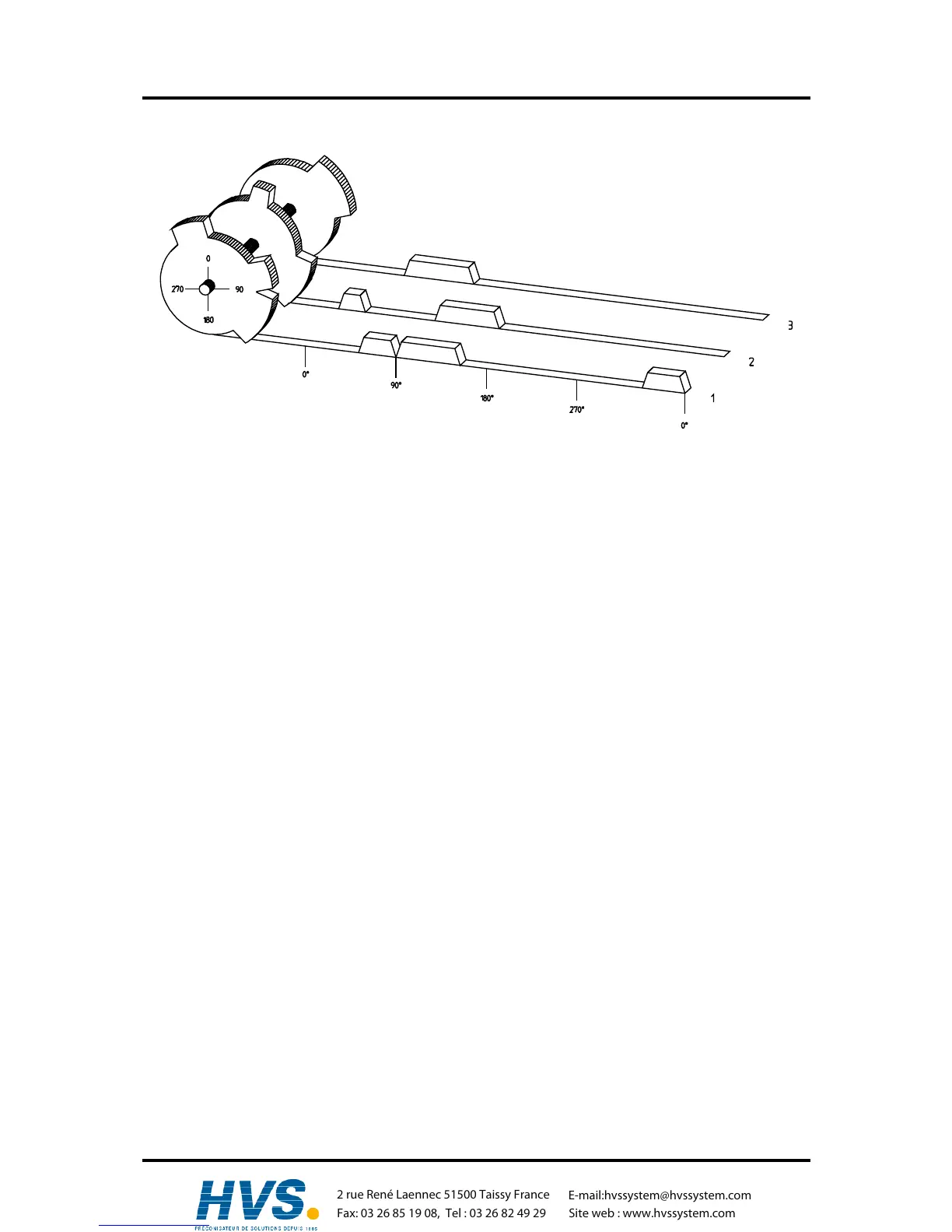
Diagram: Principles of a Cam Switch Unit
A principle for better comprehension of the function of a Cam Switch Unit is here presented. It has 3
outputs with the following cams:
Output 1: Cam 1: Switch-ON position60° Switch-OFF position 85°
Cam 2: Switch-ON position95° Switch-OFF position 145°
Cam 3: Switch-ON position325° Switch-OFF position 355°
Output 2: Cam 1: Switch-ON position5° Switch-OFF position 20°
Cam 2: Switch-ON position95° Switch-OFF position 145°
Output 3: Cam 1: Switch-ON position30° Switch-OFF position 85°
The positions of the output signals, here presented as three tracks, occur when the three cam disks
turn anti-clockwise past a sensor, which scans the cams on the 0°-axis.
In a mechanical cam switch unit, the switch interval, i.e. the range between switch-ON and switch-OFF
position are determined by the length of the cam. The length and the position of the cam can only be
varied marginally and this is mechanically highly demanding and time consuming. With CamCon such
adjustments can be realised in a fraction of time; in addition, there can be any number of tracks. A
measuring system which is fitted to the device reports the position to the CamCon. The CamCon
compares it with the programmed switch-ON and Switch-OFF positions of all outputs. If the position
lies in the range of a programmed switch-ON / switch-OFF position (cam), then the respective outputs
are active.
,Version from: Aug. 04 Page: 8
2 rue René Laennec 51500 Taissy France
Fax: 03 26 85 19 08, Tel : 03 26 82 49 29
E-mail:hvssystem@hvssystem.com
Site web : www.hvssystem.com