Digitronic Digital Cam Switch Unit
Automationsanlagen GmbH CamCon DC50/51
TABLE OF CONTENTS
1. Introduction ..........................................................................................................................................8
2. Operating Pinciples..............................................................................................................................9
2.1. Speed Compensation .....................................................................................................................10
2.1.1. Measuring delay time for Speed Compensation..........................................................................12
2.1.1.1. Measuring delay time through actual differences .....................................................................12
2.1.1.2. Measuring delay time by means of different measuring points.................................................12
2.1.2. Speed Compensation using off-centre pressure, e.g. brake functions........................................13
2.1.3. Separate delay time for Speed Compensation of switch-ON and switch-OFF points .................14
2.2. Time - Cam.....................................................................................................................................14
3. Installation..........................................................................................................................................15
3.1. Dimensions .....................................................................................................................................15
4. Electrical connections ........................................................................................................................16
4.1. Pin allocation of the CamCon .........................................................................................................16
4.1.1. Pin allocation of the analog output...............................................................................................16
4.1.2. Pin allocation of the SSI measuring system.................................................................................16
4.1.3. Pin allocation of the incremental measuring system....................................................................17
4.1.4. Pin allocation of the inputs...........................................................................................................17
4.1.5. Pin allocation of the outputs.........................................................................................................17
4.1.6. Pin allocation of the voltage supply..............................................................................................18
4.1.7. Pin allocation of the serial interface.............................................................................................18
4.1.7.1. Pin allocation of the serial RS232 interface..............................................................................18
4.1.7.2. Pin allocation of the serial RS485 interface..............................................................................19
4.1.8. Pin allocation of the external interface.........................................................................................20
4.2. The measuring system....................................................................................................................21
4.2.1. SSI Measuring system input ........................................................................................................21
4.2.2. Parallel measuring system input..................................................................................................21
4.2.3. Incremental measuring system input...........................................................................................22
4.2.3.1. Incremental measuring system input with 5V RS422 level.......................................................22
4.2.3.2. Incremental measuring system input with 24V PNP level.........................................................22
4.2.3.3. Incremental Hiperface measuring system input with SINCOS level.........................................23
4.2.4. Analog measuring system input...................................................................................................23
4.2.5. PLL measuring system input........................................................................................................24
4.2.6. Timer as a measuring system......................................................................................................24
4.2.7. RS232 as a measuring system....................................................................................................24
4.3. The outputs.....................................................................................................................................25
4.3.1. The 40mA outputs (only CamCon device with aluminium back wall)..........................................25
4.3.2. The 500mA outputs......................................................................................................................25
4.4. The inputs .......................................................................................................................................25
4.5. Precautionary measures for welding work......................................................................................25
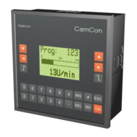
5. Outline of the operator terminal .........................................................................................................26
5.1. Frontview CamCon .........................................................................................................................26
5.2. The liquid crystal display (LCD) ......................................................................................................26
5.3. Contrast setting...............................................................................................................................26
5.4. The keyboard..................................................................................................................................26
5.5. Outline of key functions...................................................................................................................27
5.6. Menu selection................................................................................................................................27
5.7. Selection of a menu point ...............................................................................................................27
5.8. Text input ........................................................................................................................................28
6. Commissioning ..................................................................................................................................29
7. Operation of the CamCon..................................................................................................................31
7.1. The main menu...............................................................................................................................31
7.2. The standard display.......................................................................................................................31
,Version from: Aug. 04 Page: 3