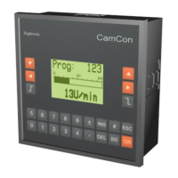
Digitronic Digital Cam Switch Unit
Automationsanlagen GmbH CamCon DC50/51
- Mode of the serial interface
- Unit number
- additional options of the e.g. PLC option
or PLC option with text display
- Number of internal analog outputs
- CPU - Speed (clock) 16 or 25 Mhz
- Hardware PLC - acceleration (on/off)
- Configuration of the analog cam 1,2, up to 13.
- Input and display format
- Minimal input value ( - 10V)
- Maximum input value ( + 10V)
- Input number for switch to dis.value
- Output value if switch off
- Interpolation yes/no
For each of the analog cam the CamCon displays one more information menu. A maximum of 13
analog cam are possible.
- Adjustements for OP-functions.
For each line of a menu-page information-menus are
shown.
8.1. Stack Info
If a non-defined error happens while the CamCon is in operation, the user is able to controll the stack-
variables' allocation which helps the software developers detection of effects. Use to stack-information-
menu for this purpose.
Please note the information shown on screen. At the moment, we are able to show a maximum of 6
stack-informnation menus. Please note their content and send it by fax to. +49/6126/945342.
Note: Using a CamCon DC16; 40; 50/51 and DC90 only 4 stack-menus are shown. these are
called iotask, rs232task, dc40task and main A CamCon DC 115 also shows tasks
called DC115_0, DC115_1; a CamCon DC300 also shows DC300.
,Version from: Aug. 04 Page: 78
2 rue René Laennec 51500 Taissy France
Fax: 03 26 85 19 08, Tel : 03 26 82 49 29
E-mail:hvssystem@hvssystem.com
Site web : www.hvssystem.com