102
160XT 180XT 210XT
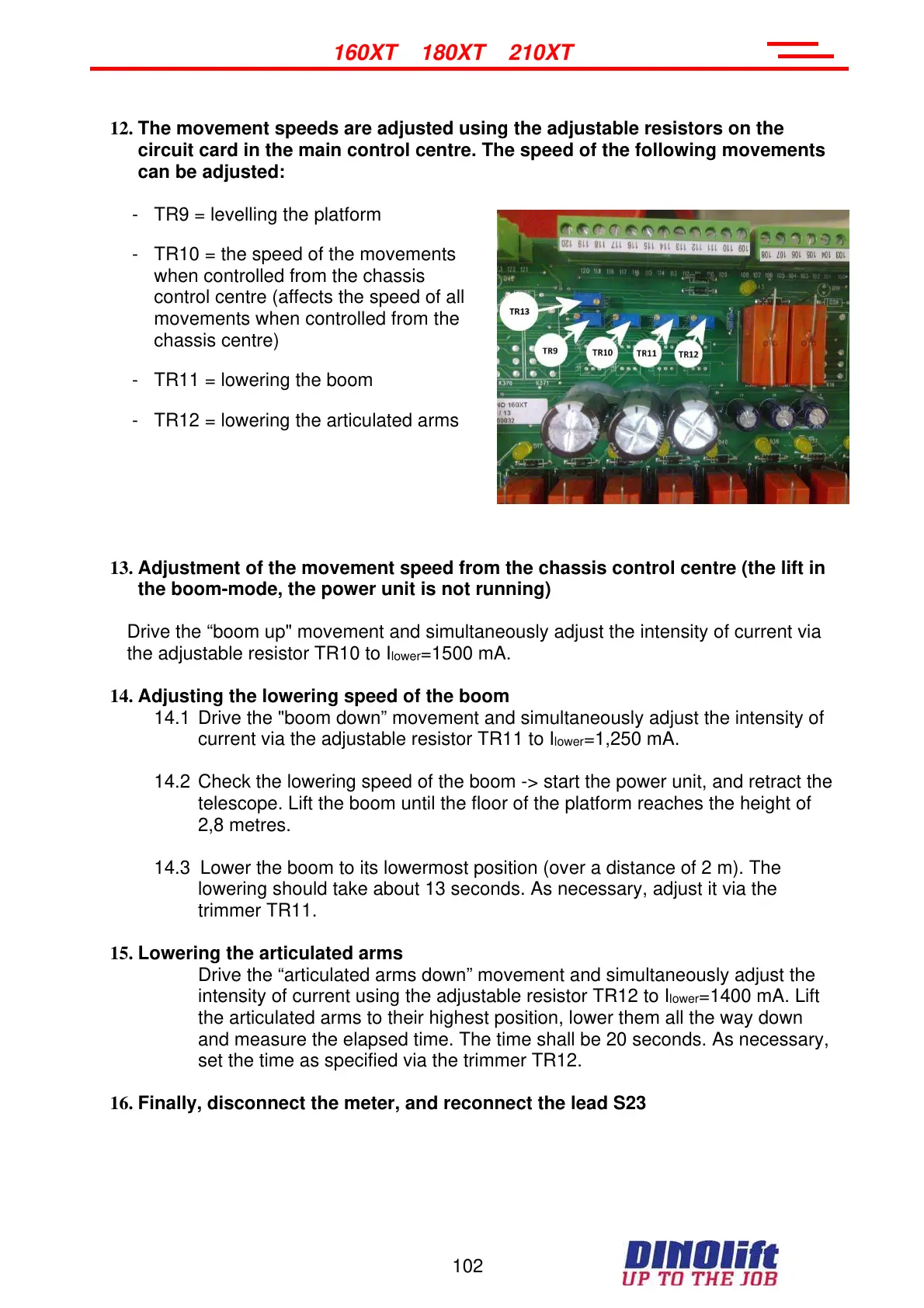
12. The movement speeds are adjusted using the adjustable resistors on the
circuit card in the main control centre. The speed of the following movements
can be adjusted:
- TR9 = levelling the platform
- TR10 = the speed of the movements
when controlled from the chassis
control centre (affects the speed of all
movements when controlled from the
chassis centre)
- TR11 = lowering the boom
- TR12 = lowering the articulated arms
13. Adjustment of the movement speed from the chassis control centre (the lift in
the boom-mode, the power unit is not running)
Drive the “boom up" movement and simultaneously adjust the intensity of current via
the adjustable resistor TR10 to I
lower
=1500 mA.
14. Adjusting the lowering speed of the boom
14.1 Drive the "boom down” movement and simultaneously adjust the intensity of
current via the adjustable resistor TR11 to I
lower
=1,250 mA.
14.2 Check the lowering speed of the boom -> start the power unit, and retract the
telescope. Lift the boom until the floor of the platform reaches the height of
2,8 metres.
14.3 Lower the boom to its lowermost position (over a distance of 2 m). The
lowering should take about 13 seconds. As necessary, adjust it via the
trimmer TR11.
15. Lowering the articulated arms
Drive the “articulated arms down” movement and simultaneously adjust the
intensity of current using the adjustable resistor TR12 to I
lower
=1400 mA. Lift
the articulated arms to their highest position, lower them all the way down
and measure the elapsed time. The time shall be 20 seconds. As necessary,
set the time as specified via the trimmer TR12.
16. Finally, disconnect the meter, and reconnect the lead S23
Courtesy of Crane.Market